Samsung Electronics 7-1
7. Block Diagram
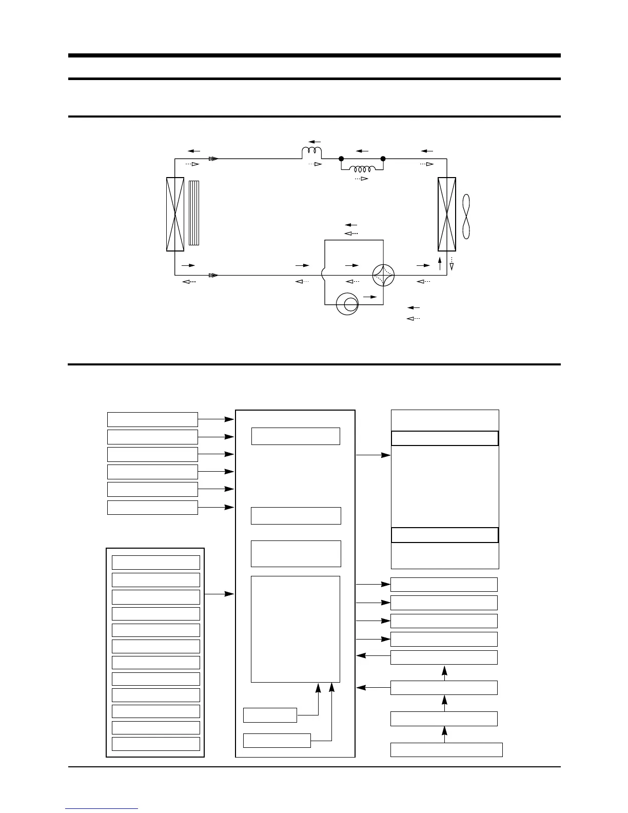
7-1 Refrigerating Cycle Block Diagram
Capillay tube
Check V/V
T1
T2
Heat
exchanger
(Evaporator)
Heat
exchanger
(Condenser)
Compressor
4-way valve
Cooling
Heating
fan
Propeller fan
7-2 Basic Structure
7-2-1 Micom Control Diagram
A/D converter
• 4-way valve control
• Swing motor control
• Compressor control
• Buzzer control
• Temperature control
• Fan motor control
Reset Circuit
Led display control
Remocon Single
Receiving
Compressor
Fan motor
Power circuit (DC 5V)
Oscillation Circuit
Membrane Pad control
• Temp.set(
↑, ↓
)
• Operation, Mode
• Swing, Sleep
• Fan select, Timer
• Remocon single control
MAIN MICOM
4-Way
Swing motor
Powercircuit (DC 12V)
Powercircuit (DC 12V)
Down Trans (AC15V)
Power input (AC230V), (AC115V)
(Key operation)
(Remocon control)
Operation
Air swing
Timer
Sleep
Fan speed (high)
Fan speed (med)
Fan speed (low)
Fan
Cool
HEAT
Temp.setting(↑)
Temp.setting(↓)
(Remote Control)
Indoor Temperature Sensor
Outdoor Temperature Sensor
Room Temperature Sensor
Deice Temperature Option
Deice Time Option
Receiving Unit of Remocon
(J)DB98-03455A(1)-2 9/12/01 1:26 PM Page 7-1