
G
gwashingtonJul 31, 2025
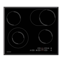
How to check Motor DC resistance on a Samsung C61R1AAMST Hob?
- JJohn VaughnJul 31, 2025
To check the Motor DC resistance on your Samsung Hob, measure between pin No.1 and pin No.3. The resistance should be 1.65K~1.8K?.
How to check Motor DC resistance on a Samsung C61R1AAMST Hob?
To check the Motor DC resistance on your Samsung Hob, measure between pin No.1 and pin No.3. The resistance should be 1.65K~1.8K?.
Explains the principle of induction heating for the hob's operation.
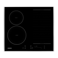
Lists and compares features of the basic and new induction hob models.
Provides a comparative table of specifications for basic and new models.
Details the accessories included with the induction hob, like screws and cables.
Provides instructions for replacing the ceramic glass top plate of the hob.
Details the procedure for replacing the control panel assembly.
Step-by-step guide for replacing the induction working coil assembly.
Instructions on how to replace the bracket-wire component.
Procedure for replacing the main induction module assembly.
Guide for replacing the case burner assembly, including terminal block.
Outlines methods for checking the condition of key components.
Lists and explains various error codes and their potential causes and solutions.
Provides troubleshooting steps for power and heating-related electrical issues.
Diagrams showing the exploded assembly of the induction hob components.
Lists the main parts of the hob with their respective codes and specifications.
Detailed parts list for the assembly of the induction working coils.
Lists components that make up the induction module assembly.
Catalog of standard parts, such as screws, used in the appliance.
Diagram of the main PCB, showing its components and connections.
Diagram of the touch control PCB and its component layout.
Diagram of the inverter module PCB and its components.
Illustrates the overall wiring connections between different modules of the hob.
Detailed schematic of the main PCB, showing circuit design.
Schematic detailing the circuit design of the touch control PCB.
Schematic outlining the circuit design of the inverter module PCB.
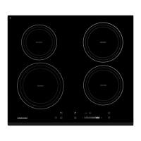
| Hob type | Ceramic |
|---|---|
| Product color | Black |
| Hob width size | 57.5 cm |
| Appliance placement | Built-in |
| Number of cooking zones | 4 zone(s) |
| Number of gas cooking zones | 0 zone(s) |
| Child lock | Yes |
| Control type | Touch |
| Built-in display | No |
| Control position | Front |
| Number of power levels | 9 |
| Connected load (gas) | 0 W |
| Connected load (electric) | 6000 W |
| Package depth | 622 mm |
| Package width | 692 mm |
| Package height | 130 mm |
| Package weight | 10000 g |
| Depth | 52.6 mm |
|---|---|
| Width | 575 mm |
| Height | 505 mm |
| Weight | 7500 g |