EasyManua.ls Logo

Samsung CL21S8WKX/XAX User Manual

Samsung CL21S8WKX/XAX
91 pages
To Next Page IconTo Next Page
Page #1 background imageLoading...
Page #1 background image
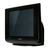
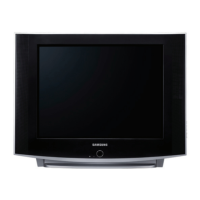
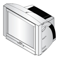
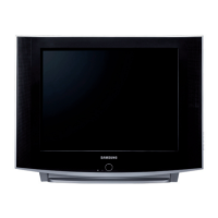
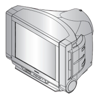
COLOR TELEVISION RECEIVER
Chassis : KS2A(N_REV.2)
Model : CL21S8WKX/XAX CL21S8W7X/RCL
CL21S8W7X/XAO CL21S8WKX/RCL
CL21S8WKX/XAP CL21S8WKX/XAO
CL21S8WKX/STR
COLOR TELEVISION RECEIVER CONTENTS
Precautions
Reference Information
Specifications
Alignment and Adjustments
Troubleshooting
Exploded Views and Parts List
Electrical Parts List
Block Diagrams
Wiring Diagram
Schematic Diagrams
1.
2.
3.
4.
5.
6.
7.
8.
9.
10.
Question and Answer IconNeed help?

Do you have a question about the Samsung CL21S8WKX/XAX and is the answer not in the manual?

Samsung CL21S8WKX/XAX Specifications

General IconGeneral
BrandSamsung
ModelCL21S8WKX/XAX
CategoryTV
LanguageEnglish

Summary

1. Precautions

1-1 Safety Precautions

Essential safety guidelines for servicing to prevent hazards like shock and X-rays.

1-2 Servicing Precautions

Specific precautions to follow during the servicing process itself.

1-3 Precautions for Electrostatically Sensitive Devices (ESDs)

Guidelines for handling sensitive electronic components to prevent ESD damage.

3. Specifications

4. Alignment and Adjustments

4-3 High Voltage Check

Instructions for safely checking high voltage levels on the chassis.

5. Troubleshooting

5-1 No Power

Troubleshooting flowchart for issues related to the unit not powering on.

5-2 No Raster (Sound OK)

Troubleshooting guide for when the screen shows no raster but sound is present.

5-3 No Sound

Troubleshooting flowchart for issues where there is no audio output.

5-4 Horizontal Lines Appear on screen

Troubleshooting steps for identifying and resolving horizontal lines on the screen.

8. Block Diagrams

8-1 Power Diagram

Block diagram illustrating the power supply and distribution system.

8-2 Block Diagram

High-level block diagram showing major functional modules and their connections.

9. Wiring Diagram

10. Schematic Diagrams

10-1 MAIN 1/4 (WITH EW)

Part 1 of the main schematic diagram showing the EW circuit.

10-2 MAIN 2/4

Part 2 of the main schematic diagram, detailing ICs and modules.

10-3 MAIN 3/4

Part 3 of the main schematic diagram, showing MCU and peripheral connections.

10-4 MAIN 4/4

Part 4 of the main schematic diagram, detailing power and control signals.

Related product manuals