Do you have a question about the Samsung CL25M6WKX/XAX and is the answer not in the manual?
Essential safety measures for servicing to prevent electrical shock and hazards.
Technical specifications of the television receiver, including system, channels, and picture tube.
Procedures for safely disassembling and reassembling the television set.
Guide to preadjustment, service mode operations, and various picture adjustments.
Diagnostic flowcharts and steps for identifying and resolving common TV issues.
Visual breakdown of TV components with associated part numbers for various models.
Detailed list of electrical components and their part numbers for specific models.
Functional block diagram illustrating the signal flow and key components of the K57A chassis.
Diagram showing interconnections between major assemblies for the K57A chassis.
Circuit schematics for different sections of the television, including main boards and CRT.
Essential safety measures for servicing to prevent electrical shock and hazards.
Specific precautions to be followed during the servicing of the unit.
Guidelines for handling sensitive electronic components to prevent static discharge damage.
Technical specifications of the television receiver, including system, channels, and picture tube.
List of integrated circuits used in the receiver with their location, specification, and description.
Illustrations of semiconductor component base diagrams for identification and understanding.
Procedure for safely removing the back cover of the television set.
Steps for removing the main circuit board, including safety warnings.
Instructions on how to remove the speakers from the unit.
Detailed procedure and caution for removing the Cathode Ray Tube (CRT).
Initial adjustments needed after component replacement like EEPROM or CRT.
Guide to entering and navigating the factory service mode for various adjustments.
Covers general adjustments, degaussing, high voltage, focus, purity, and white balance.
Diagnostic flowchart for troubleshooting power-related issues in the receiver.
Troubleshooting steps for when the television has sound but no video.
Diagnostic guide for resolving issues where video is present but there is no sound.
Troubleshooting flowchart for problems related to horizontal lines or screen display.
Exploded view and parts list for the CL25M6WKX/XAX model.
Exploded view and parts list for the CL25M6WKX/XAP model.
Exploded view and parts list for the CL21M6WKX/STR model.
Detailed list of electrical components and their part numbers for CL25M6WKX/XAX.
Detailed list of electrical components and their part numbers for CL25M6WKX/XAP.
Detailed list of electrical components and their part numbers for CL21M6WKX/STR.
Functional block diagram illustrating the signal flow and key components of the K57A chassis.
Wiring diagram showing the interconnections between major assemblies for the K57A chassis.
Schematic diagram for the main board, part 1 of 3.
Schematic diagram for the main board, part 2 of 3.
Schematic diagram for the main board, part 3 of 3.
Schematic diagram illustrating the CRT section and related components.
| Brand | Samsung |
|---|---|
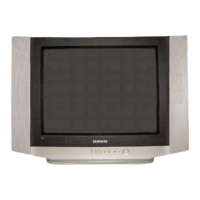
| Model | CL25M6WKX/XAX |
| Category | TV Receiver |
| Language | English |