Do you have a question about the Samsung CS21M16MJZXNWT and is the answer not in the manual?
Safety measures covering protective devices, leakage current, X-ray limits, and high voltage.
Guidelines for safe component handling, power disconnection, and unit assembly.
Techniques to prevent static discharge damage to sensitive electronic components.
TV system, channel bands, IF frequencies, picture tube, and power requirements.
List of ICs used, their specifications, location, and manufacturer.
Pinout diagrams for transistors, diodes, and ICs, aiding in component identification.
Step-by-step guide on how to safely remove the television's back cover.
Instructions for removing the main board, including high-voltage discharge warnings.
Method for removing the speaker assembly from the TV chassis.
Procedures and safety warnings for removing the Cathode Ray Tube (CRT).
Steps for initial adjustments after EEPROM or CRT replacement.
How to enter and navigate the service mode for TV adjustments.
Table of adjustable parameters, their ranges, and initial values.
Selection of optional features and settings via service mode option bytes.
How to reset TV settings to factory defaults for inspection purposes.
Guidelines for general adjustments and automatic degaussing procedure.
Checking high voltage and adjusting picture focus for clarity.
Procedures for adjusting color purity and white balance for accurate color.
Aligning red, green, and blue picture elements for correct convergence.
Adjustments for RF AGC, sub-color settings, and overall picture geometry.
Flowchart to diagnose and fix issues with no video but raster, and no sound.
Flowchart for diagnosing and resolving problems related to the TV not powering on.
Flowchart to identify and fix issues where video is absent but sound is present.
Flowchart for diagnosing and resolving problems with no sound but video is functional.
Diagnosing issues where the Teletext function is not working.
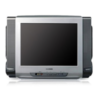
Visual breakdown and list of parts for the CS21M16MJZXNWT model.
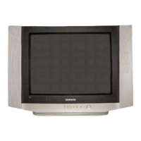
Visual breakdown and list of parts for the CS21K30MJZXNWT model.
Detailed list of electrical components with location, code, and specification.
Diagram showing the functional blocks and signal paths of the KS9A chassis.
Diagram illustrating the electrical connections between components in the KS9A chassis.
Circuit diagrams for the main processor and test points.
Circuit diagrams for sound processing and SCART interface.
Circuit diagrams for sound processing and RCA interface.
Circuit diagrams for power supply, CRT, and deflection systems.
Circuit diagram for the mono audio sub-processor board.
Circuit diagram for the stereo audio sub-processor board.
| Brand | Samsung |
|---|---|
| Model | CS21M16MJZXNWT |
| Category | TV Receiver |
| Language | English |