Do you have a question about the Samsung CLX-3185W and is the answer not in the manual?
Essential safety warnings for servicing the product by factory trained technicians.
Guidance on avoiding electric shock, fire hazards, and handling toxic materials.
Instructions for safe handling of the product to prevent injury or damage.
Careful procedures for replacing parts and disassembling the machine.
Warnings about potential bodily injury from high temperatures and rotating parts.
Techniques to prevent damage to components from static electricity.
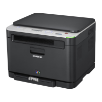
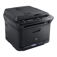
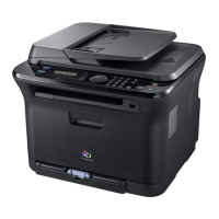
Overview of the product's basic specifications and features.
Detailed specifications for print, scan, copy, fax, paper handling, and drivers.
Detailed specifications related to the telephone functionality of the device.
Detailed specifications for the fax capabilities of the machine.
Information on paper input capacity and output capabilities.
Details on supported operating systems and driver features.
Specifications for USB, Network, and Wireless interfaces.
List of consumable parts like toner cartridges and imaging units.
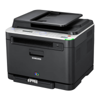
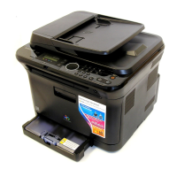
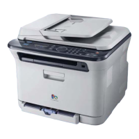
Comparison of the CLX-3185 series with competing models.
Description of the main components and operating principles.
Explanation of the main parts comprising the printer system.
Detailed description of the printer's hardware components and configuration.
Information about Customer Replaceable Unit Monitor (CRUM) for cartridges.
Description of the software architecture and its components.
Overview of the printer's software architecture.
Function and role of the Language Monitor in the software system.
Function and role of the Status Monitor in the software system.
Description of the printer's network interface capabilities.
Interaction between the printer driver and the status monitor.
Diagram illustrating the system firmware flow.
Information on alarm conditions and toner/transfer belt status.
List of possible error messages and their meanings.
Explanation of CRUM memory and stored information.
Flowchart detailing the printer initialization process.
Essential precautions before starting disassembly or reassembly.
List of parts with their replacement intervals and part numbers.
Guidelines for cleaning the printer to maintain print quality.
Important information and warnings before disassembling specific units.
A detailed list of screws used for various parts during disassembly.
Step-by-step instructions for disassembling printer components.
Procedure for removing the printer's covers.
Procedure for disassembling the Automatic Document Feeder (ADF).
Procedure for removing the Operation Panel (OPE) unit.
Procedure for removing the ADF sheet.
Procedure for disassembling the scanner assembly.
Procedure for removing the Contact Image Sensor (CIS) unit.
Procedure for removing the middle cover of the printer.
Procedure for removing the Wireless LAN Printed Board Assembly.
Procedure for removing the Intermediate Transfer Belt (ITB).
Procedure for removing the fuser unit, with heat warning.
Procedure for removing the High Voltage Power Supply (HVPS) board.
Procedure for removing the Main Printed Board Assembly (PBA).
Procedure for removing the Switching Mode Power Supply (SMPS) board.
Procedure for removing the Laser Scanning Unit (LSU).
Procedure for removing the holder pad.
Procedure for removing the transfer roller assembly.
Procedure for removing the pick up roller assembly.
Procedure for removing the main drive unit.
Procedures for aligning and adjusting printer functions.
Description of the printer's control panel buttons and functions.
Explanation of the status LED colors and their meanings.
Diagram and explanation of the paper path within the printer.
Overview of the menus accessible from the control panel.
Instructions for upgrading the printer's firmware.
Procedures for entering and using the service technician mode.
Instructions for entering and using the EDC mode for diagnostics.
Troubleshooting guide for image defects that appear periodically.
List of error messages and their corresponding solutions.
General troubleshooting procedures for common printer issues.
Systematic approach to diagnosing printer problems.
A checklist to verify printer functionality and identify issues.
Solutions for common issues where the printer does not print.
Guidance for resolving various print quality issues.
Troubleshooting common issues encountered on Windows operating systems.
Troubleshooting common issues encountered on Macintosh operating systems.
Troubleshooting common issues encountered on Linux operating systems.
Solutions for major printer malfunctions like multi-feeding and no power.
Troubleshooting for fax and phone related issues.
Troubleshooting for common problems related to copying.
Troubleshooting for issues related to the scanner and operator panel.
High-level block diagram of the printer's internal system.
Wiring and connection diagram for the 4-in-1 model.
Wiring and connection diagram for the 3-in-1 model.
Recommended tools for performing troubleshooting procedures.
Glossary of acronyms and abbreviations used in the manual.
Guidance on selecting an appropriate environment for printer installation.
Information on the standard test pattern for A4 ISO 19752.
| Type | All-in-One Printer |
|---|---|
| Print Technology | Laser |
| Functions | Print, Copy, Scan, Fax |
| Print Speed (Color) | 4 ppm |
| Print Resolution | 2400 x 600 dpi |
| Monthly Duty Cycle | 20, 000 pages |
| Display | 2-line LCD |
| Duplex Printing | Manual |
| Memory | 64 MB |
| Paper Handling Input (Standard) | 150 sheets |
| Scan Resolution | 4800 x 4800 dpi |
| Copy Speed (Color) | 4 cpm |
| Copy Resolution | 600 x 600 dpi |
| Fax Speed | 33.6 kbps |
| Paper Capacity | 150 sheets |
| Connectivity | Wireless |
| Scanner Type | Flatbed |
| Scan Resolution (Optical) | 1200 x 1200 dpi |
| Supported Operating Systems | Windows, Mac |