EasyManua.ls Logo

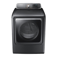
Samsung DV56H9000G User Manual

Samsung DV56H9000G
24 pages
To Next Page IconTo Next Page
Page #1 background imageLoading...
Page #1 background image
1
CLOTHES DRYER
Technical Information
CAUTION
All safety information must be followed as provided in Service Manual of
DV56H9000E(G)*.
WARNING
To avoid risk of electrical shock, personal injury or death, disconnect power to dryer
before servicing, unless testing requires power.
Code No. : DC68-03171F_EN
IMPORTANT SAFETY NOTICE – “For Technicians only” This service data sheet is intended for
use by persons having electrical, electronic, and mechanical experience and knowledge at a level
generally considered acceptable in the appliance repair trade. Any attempt to repair a major
appliance may result in personal injury and property damage. The manufacturer or seller cannot
be responsible, nor assume any liability for injury or damage of any kind arising from the use of
this data sheet.
• Duetopossibilityofpersonalinjuryorpropertydamage,alwayscontactanauthorized
technician for servicing or repair of this unit.
• RefertoServiceManual(DV56H9000E(G)*)fordetailedinstallation,operating,testing,
troubleshooting, and disassembly instructions.
DV9000HA DRY_TECH MANUAL_DC68-03171F_EN.indd 1 2014-1-17 14:00:25
Questions and Answers:

Samsung DV56H9000G Specifications

General IconGeneral
BrandSamsung
ModelDV56H9000G
CategoryDryer
LanguageEnglish

Summary

Important Safety Notice for Technicians

Alignment and Adjustments Guide

Error Items and Diagnostic Codes

Lists error codes, triggers, and recommended actions for dryer malfunctions.

Test Mode Operations

Instructions for entering and using continuous run mode for dryer testing.

Service Mode Entry and Functions

Details on accessing Service Mode, including sensor data and cycle count.

Software Version Identification

Procedure to display and understand the dryer's software version.

Data Display Mode Navigation

How to enter and cycle through temperature and sensor data display modes.

System Check Mode Procedure

Steps to activate System Check Mode and its operational sequence.

Trouble Diagnosis Guidelines

Precautions and general steps for diagnosing and repairing electronic components.

Trouble Shooting and Repair

Component Electrical Testing

Electrical testing procedures and resistance values for key dryer components.

Gas Model Specific Checks

Resistance values for gas dryer components like sensors, igniter, and gas valve.

Sensor and Thermistor Checks

Testing methods and expected resistance for sensor bars and thermistors.

3-Wire System Electrical Connections

Instructions for properly connecting a 3-wire power cord to the dryer.

4-Wire System Electrical Connections

Instructions for properly connecting a 4-wire power cord to the dryer.

Wiring Diagrams

Related product manuals