Troubleshooting _ 36
4-5. COMPONENT TESTING PROCEDURES
WARNING
To avoid risk of electrical shock, personal injury or death; disconnect power to dryer before servicing, unless testing
requires power.
■ Component electrical testing (with ohmmeter)
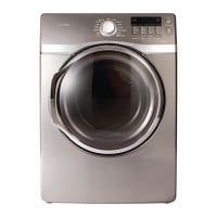
• Thermistor resistance 10K Ω at 25°C 77°F (2P-Blue & Red wire)
• Thermostat 1 resistance < 1Ω (White & Yellow wire)
Thermostat 1
Thermistor
85 °C, 25A thermal cut-off
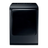
• Thermostat 3 resistance < 1Ω (Red & Black wire)
- If resistance is
replace thermostat 3.
• Thermostat 2 resistance < 1Ω (Blue & Black wire)
- If resistance is
replace thermostat 2.
•
[DUAL] Heater resistance 13 Ω (PIN 2-3) Heater resistance 34 Ω (PIN 1-2)
- If resistance is replace Heater.
•
[SINGLE] Heater resistance 10 Ω (PIN 1-3)
- If resistance is replace Heater.
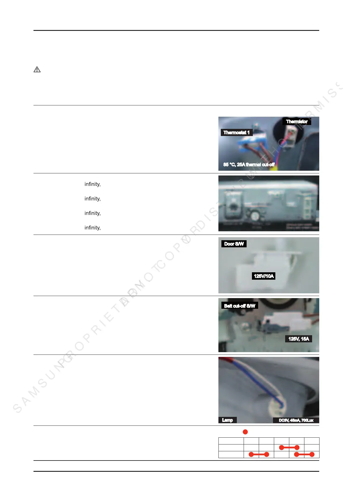
• Measure resistance of the following terminal
1. Door switch knob: open
Terminal : “COM” - “NC” (1-3) < 1Ω
Terminal : “COM” - “NO” (1-2) : ∞ Ω
2. Door switch push: On
Terminal : “COM” - “NC” (1-3) : ∞ Ω
Terminal : “COM” - “NO” (1-2) < 1Ω
Door S/W
125V/10A
• Belt Cut-off S/W
- Lever open: Resistance value < 1Ω
- Lever push: Resistance value ∞ Ω
Belt cut-off S/W
125V, 15A
• Lamp resistance : ∞ Ω, (-) : BLU, (+) : WHT
DC3V, 45mA, 700Lux
Lamp
• Motor (Electronic & GAS)
Contacts (
: Contact closed)
Function 1M 2M 3M 5M 6M
Start
Run
This document can not be used without Samsung's authorization”
SAMSUNG PROPRIETARY. DO NOT COPY OR DISTRIBUTE WITHOUT PERMISSION