Do you have a question about the Samsung DV448AEP and is the answer not in the manual?
Precautions to ensure safety during servicing and repair of the dryer.
Crucial safety precautions to prevent fire, electric shock, and injury when using the dryer.
Details on electrical requirements, wiring, and grounding for the dryer.
Information regarding the power supply and grounding requirements for gas dryers.
Guidelines for correct grounding and polarization of 120V wall outlets for safety.
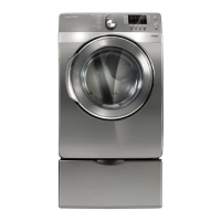
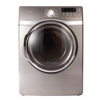
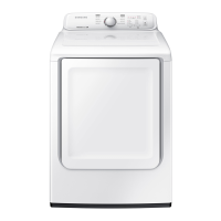
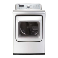
Detailed description of the various features and functionalities of the clothes dryer.
Technical specifications including dimensions, weight, and power consumption of the dryer.
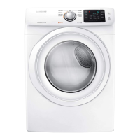
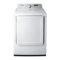
Comparison of the dryer's specifications against other models.
Specifications for optional accessories available for the dryer.
List of necessary tools required for disassembling and reassembling the dryer.
Visual guide for disassembling the dryer, focusing on panel control removal.
Procedure for removing the main Printed Circuit Board (PCB) assembly.
Steps for safely removing the top cover of the dryer.
Continued steps for disassembling the dryer's door assembly.
Final steps for removing the dryer's door and door seal.
Instructions for removing the front frame of the dryer.
Further steps for removing the front part of the drum assembly.
Detailed steps for removing the dryer's drum front and related components.
Procedure for removing the main drum of the dryer.
Steps for removing the dryer's temperature sensors.
Instructions for removing the heater and thermostat components.
Further steps for disassembling the motor assembly.
Continued steps for removing the motor assembly, including fan and spring plates.
Final steps for removing the motor assembly, including holder and roller shafts.
Additional steps for removing the drum back and related components.
Steps for removing the drum back, including duct exhaust.
Procedure for removing the duct exhaust assembly.
Continued steps for reversing the dryer door, focusing on lever and frame components.
Further steps for reversing the dryer door, including hinge and guide reassembly.
Final steps for door reversal, including cushion cover and frame reassembly.
List of error displays, triggers, and corresponding actions for troubleshooting.
Instructions for entering and using various test modes for diagnostics.
Procedure for activating and using the system check mode for dryer diagnostics.
Guide for diagnosing and repairing common dryer problems.
Important precautions to take before performing repairs or replacing parts.
Table detailing problems, their causes, and recommended solutions for the dryer.
Step-by-step diagnosis and actions for common dryer symptoms.
Troubleshooting steps for when the dryer drum fails to operate.
Diagnostic steps to address issues where clothes are not drying properly.
Troubleshooting steps for a non-functional dryer lamp.
Guidance on identifying and resolving abnormal noises coming from the dryer.
Procedures for testing individual dryer components using an ohmmeter.
Testing procedures for the motor's centrifugal switch.
Specific component testing procedures applicable to gas models.
Testing procedures for sensor bars and temperature sensors.
Standards and rules for managing material codes and naming.
Exploded view diagram of the main components of the clothes dryer.
Parts list for the DV5471AEP/XAA model, including service availability.
Exploded view of the frame front and door assembly for DV5471AEP/XAA.
Exploded view of the frame front and door assembly for DV5471AEW/XAA.
Parts list for the control panel assembly of the DV5471AEP/XAA model.
Parts list for the control panel assembly of the DV5471AEW/XAA model.
Exploded view of drum parts for the DV5471AEP/XAA model.
Exploded view of drum parts for the DV5471AEP/XAA model.
Exploded view of the motor assembly for the DV5471AEP/XAA model.
Exploded view of the motor assembly for the DV5471AEP/XAA model.
Exploded view of the duct heater assembly for the DV5471AEP/XAA model.
Exploded view of the duct heater assembly for the DV5471AEP/XAA model.
Exploded view of the duct burner assembly for the DV5471AGP/XAA model.
Exploded view of the duct burner assembly for the DV5471AGP/XAA model.
List of small parts for the DV5471AEP/XAA model.
List of small parts for the DV5471AEP/XAA model.
Parts list for DV5471AEP/XAA model, categorized by screw type.
Parts list for DV5471AEP/XAA model, categorized by screw type.
Detailed parts list for screws used in the DV5471AEP/XAA model.
Detailed parts list for screws used in the DV5471AEP/XAA model.
Diagram showing the layout and connectors of the main Printed Circuit Board.
Detailed pinout and function descriptions for the main PBA terminals.
Diagram showing the layout and connectors of the sub Printed Circuit Board.
Detailed pinout and function descriptions for the sub PBA terminals.
Wiring diagram specific to the electric dryer model.
Wiring diagram specific to the gas dryer model.
Schematic diagram for the main control board of the dryer.
Schematic diagram for the sub control board (Microcontroller Unit).
Schematic diagram for the sub control board related to the display.