
J
Jason HallAug 10, 2025
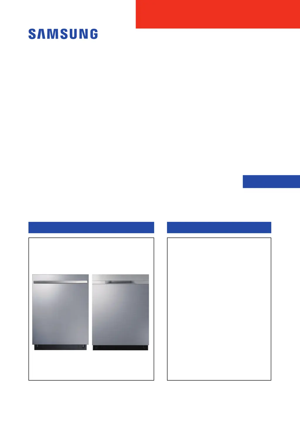
Why is my Samsung Dishwasher not draining?
- SScott JonesAug 10, 2025
Your Samsung Dishwasher might not be draining due to several reasons. A foreign object may have entered and blocked the drain pump, in which case you should remove the object. Alternatively, the drain pump itself, the Main PBA, or the Inverter PBA could be out of order, requiring repair or replacement.