EasyManua.ls Logo

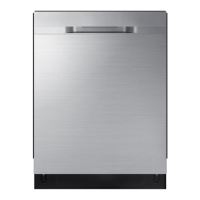
Samsung DW80R9 Series User Manual

Samsung DW80R9 Series
65 pages
To Next Page IconTo Next Page
Page #1 background imageLoading...
Page #1 background image
DISHWASHER CONTENTS
SERVICE
Manual
DISHWASHER
Model Name : DW80R9*** Series
Model Code :
DW80R9950UG/AA
DW80R9950US/AA
DW80R9950UG/AC
DW80R9950US/AC
1. Safety Instructions
2. )HDWXUHVDQG6SHFL¿FDWLRQV
3. Disassembly and Reassembly
4. Troubleshooting
5. PCB Diagram
6. Wiring Diagram
7. Reference

Questions and Answers:

Samsung DW80R9 Series Specifications

General IconGeneral
BrandSamsung
ModelDW80R9 Series
CategoryDishwasher
LanguageEnglish

Summary

SAFETY INSTRUCTIONS

SAFETY INSTRUCTIONS FOR SERVICE ENGINEERS

Essential safety guidelines for technicians performing service.

FEATURES AND SPECIFICATIONS

FEATURES

Overview of the dishwasher's key functionalities and benefits.

SPECIFICATIONS

Technical details and performance data of the dishwasher model.

COMPARING SPECIFICATIONS WITH EXISTING MODELS

Comparison of new model features against older models.

OPTIONS SPECIFICATIONS

Details on optional accessories and their specifications.

DISASSEMBLY AND REASSEMBLY

TOOLS FOR REMOVAL AND REASSEMBLY

Required tools for safely taking apart and putting back the dishwasher.

PREPARATION FOR PARTS REPLACEMENT

Steps to take before disassembling or replacing parts.

REMOVING THE UPPER RACK

Procedure for removing the upper rack assembly.

REMOVING THE 3RD RACK

Steps to remove the third rack.

Main PBA Disassembly

Instructions for disassembling the Main Printed Circuit Board Assembly.

Door Outer Panel Removal

Procedure for removing the outer door panel.

Control Panel & Handle Disassembly

Steps to disassemble the control panel and handle.

Dispenser Slide Removal

How to remove the detergent dispenser slide mechanism.

Lever, Switch, Condenser Disassembly

Disassembly of door lever, switch, and condenser components.

Assy Case Brake Removal

Procedure for removing the case brake assembly.

Water Valve Removal

Steps to remove and replace the water inlet valve.

Assy Duct Main & Rail Removal

Disassembly of the main duct and spray arm rails.

Assy Guide Water Removal

How to disassemble the water guide assembly.

Assy Cover Nozzle Removal

Procedure for removing the nozzle cover assembly.

Assy Motor Holder Removal

Steps to remove the motor holder assembly.

Motor AC Drive & Switch Removal

Disassembly of AC motor drive and micro switch.

Nozzle & Drain Hose Removal

Instructions for removing spray nozzles and the drain hose.

Assy Cover Base Removal

Procedure for removing the base cover assembly.

Door Spring Removal

How to remove the door spring mechanism.

Gear & Shaft Component Disassembly

Disassembly of gear, worm, and shaft components.

Thermistor Removal

Procedure for removing the thermistor.

Turbidity Sensor Removal

Steps to remove the turbidity sensor.

Circulation Pump Removal

How to remove the circulation pump.

Assy Base Removal

Procedure for removing the main base assembly.

Drain Pump Removal

Steps to remove the drain pump.

Motor Geared & Vane Sensor Removal

Disassembly of the geared motor and vane sensor.

Assy Sump Removal

Procedure for removing the sump assembly.

CHECKPOINTS AFTER FINISHING SERVICE

Final checks to perform after completing service or repair.

TROUBLESHOOTING

PREPARATION

Initial steps and information before troubleshooting.

SERVICE INSPECTION MODE

Guide to entering and using service diagnostic modes.

CHECK CODE TROUBLE SHOOTING

How to diagnose and resolve error codes.

PCB DIAGRAM

MAIN PCB

Diagram of the main printed circuit board and its components.

PCB DIAGRAM

Detailed diagram of the main PCB with connector assignments.

WIRING DIAGRAM

WIRING DIAGRAM

Schematic showing electrical connections and wire routing.

REFERENCE

MODEL NUMBER NAMING RULES

Explanation of how model numbers are structured and what they signify.

TERMINOLOGY

Definitions of technical terms used in the manual.

Related product manuals