THE FEATURE OF PRODUCTAIR CONDITIONER
■
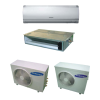
Multi Inverter(Free Joint Multi) Series
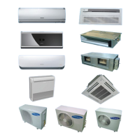
– Variable Indoor Unit Combination
(Free Joint Multi : MH040FXEA2/MH052FXEA2/
MH068FXEA4/MH080FXEA4)
– Multi Inverter(Free Joint Multi) Series delivers
comfort to 2~4 rooms with a Single Outdoor Unit
■
BLDC Inverter Compressor
– Energy Saving Function
■
Convenient Installation
■
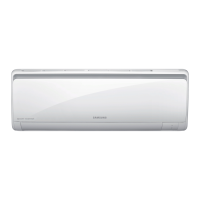
Premium Indoor Unit
SERVICE
Manual
For more information, Please access to our service web site (http://itself.sec.samsung.co.kr)
INDOOR UNIT OUTDOOR UNIT
FREE JOINT FIXED FREE JOINT FIXED
MH020FPEA MH14VP2-07 MH040FXEA2 MH14VP2X
MH023FPEA MH16VP2-07 MH052FXEA2 MH16VP2X
MH026FPEA MH16VP2-09 MH068FXEA4 MH18VP2X
MH035FPEA MH18VP2-09 MH080FXEA4 MH19VP2X
MH052FPEA MH19VP2-07 MH30VP2X
MH052FPEA1 MH19VP2-12 MH14VW2X
MH023FWEA MH30VP2-09 MH16VW2X
MH026FWEA MH30VP2-12 MH18VW2X
MH035FWEA MH14VW2-07 MH19VW2X
MH052FWEA MH16VW2-07 MH30VW2X
MH026FKEA MH16VW2-09
MH035FKEA MH18VW2-09
MH052FDEA MH19VW2-07
MH023FEEA MH19VW2-12
MH026FEEA MH30VW2-09
MH035FEEA MH30VW2-12
MULTI AIR CONDITIONER
24296A(1)_co 11/12/05 10:04 AM Page 1