F
Francis MartinezAug 12, 2025
What to do if the Timer LED is on but my Samsung Air Conditioner won't turn on?
- JJack EllisAug 12, 2025
The timer is activated, and the unit is in ready mode. Cancel the timer operation for normal operation.
What to do if the Timer LED is on but my Samsung Air Conditioner won't turn on?
The timer is activated, and the unit is in ready mode. Cancel the timer operation for normal operation.
Why doesn't my Samsung MH052FVEA Air Conditioner cool when the room is hotter than the set temperature?
This can happen after a 3-minute delay when the compressor is re-operated, or when power is turned on.
What to do if my Samsung MH052FVEA Air Conditioner's compressor stops intermittently in COOL or DRY mode, and the fan speed decreases?
The compressor might be stopping intermittently, or the indoor fan speed might be decreasing, to prevent the inside/outside air from freezing, depending on the inside/outside air temperature.
Why does my Samsung Air Conditioner's compressor stop intermittently in DRY mode?
In DRY mode, the compressor operation is automatically controlled depending on the room temperature and humidity.
Why does the compressor and indoor fan stop intermittently in HEAT mode on my Samsung MH052FVEA?
To protect the compressor from overheated air in HEAT mode, the compressor and indoor fan will stop intermittently if the room temperature exceeds the set temperature.
Why do the indoor and outdoor fans stop intermittently in HEAT mode on my Samsung Air Conditioner?
In HEAT mode, the compressor operates in a reverse cycle to remove exterior ice. The indoor and outdoor fans do not operate intermittently for within 20% of the total heater operation.
Why is the compressor of the outdoor unit operating when my Samsung MH052FVEA Air Conditioner is turned off in HEAT mode?
When the unit is turned off while de-ice is activated, the compressor continues operation for up to 12 minutes (maximum) until the deice is completed.
What to do if my Samsung MH052FVEA indoor and outdoor units do not operate properly?
Check the terminals to ensure the indoor and outdoor units are properly linked by the same number of cables and that the connecting position on the terminal is correct.
Guidelines for proper installation of the air conditioner, including height and cable management.
Instructions for safe power supply connection, including independent circuits and circuit breakers.
Safety precautions and guidelines for operating the air conditioner, including handling liquids and children.
Proper procedures for disposing of the air conditioner and its components, emphasizing environmental safety.
Miscellaneous safety guidelines covering storage, usage by vulnerable persons, and specific procedures.
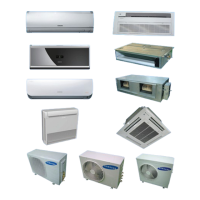
Detailed features of the Multi Inverter series, including inverter operation and indoor unit characteristics.
Technical specifications for various indoor units, including cooling/heating capacity, noise, and dimensions.
Comparison of specifications between development and comparative models, focusing on design and net weight.
Details on accessories and optional items for indoor units, including installation plates and manuals.
Information on indoor unit filters, including pre-filters, catechin filters, and deodorizing filters with maintenance instructions.
List of accessories for outdoor units (RJ040F2HXEA/RJ050F2HXEA, etc.), including drain plugs, energy labels, and flare nuts.
Details on accessories for transmitter units, including cables, cases, and installation manuals.
List of essential tools required for disassembling and reassembling air conditioner components, such as screwdrivers and spanners.
Procedures for disassembling the outdoor unit, covering common work and control out components.
Troubleshooting guide for indoor unit display errors, listing error codes and their explanations and checking points.
Troubleshooting guide for outdoor unit PCB errors, listing display codes, explanations, and remarks for various error conditions.
Step-by-step guide to setting options using the remote control, including entering setup mode and selecting options.
Guide for setting indoor unit addresses (MAIN/RMC) for AQV units, including initial settings and manual assignment.
Troubleshooting steps for manual address setting issues, covering error codes E201, E101, E203, and E121-154.
Troubleshooting steps for auto address setting issues, covering E190 error codes and pipe checking operations.
Troubleshooting for operation errors like E161, E416, E458, and E401, covering causes like simultaneous operation and fan issues.
Troubleshooting for errors encountered during try-run mode (E128, E129, E246, etc.), focusing on system defects identified during testing.
Diagnosing indoor unit temperature sensor issues (open/short) using resistance values and checking connectors.
Troubleshooting steps for indoor fan errors, checking motor connectors, foreign substances, and PCB connections.
Diagnosing communication errors between indoor and outdoor units, checking cables, PCB response, and voltage waveforms.
Troubleshooting EEPROM circuit failures, checking component condition, and replacing the PCB if necessary.
Procedures for checking outdoor controller voltages (DC Link, Main Control) and resistance values on the PFCM.
Troubleshooting steps for outdoor unit fan errors, checking connections, resistance, voltage, and operating status.
Troubleshooting compressor startup, lock, and rotation errors by checking power supply, resistance, and wiring.
Troubleshooting IPM over current errors by checking installation, service valves, compressor connection, and resistance.
Procedure for checking outdoor temperature sensors (Discharge, OLP, Condenser, Outdoor) and diagnosing errors using VIEW MODE.
Monitoring current EEV step values using VIEW MODE and checking EEV steps (A, B, C, D) for proper operation.
Safety precautions and handling guidelines for replacing PCB components, including static electricity and soldering.
Step-by-step procedure for PCB inspection and replacement, including checking for faults and setting addresses.
Exploded view diagrams and parts lists for indoor units, covering various models.
Exploded view and parts list for MH020FNEA, MH026FNEA, and MH035FNEA indoor units.
Exploded view and parts list for the MH052FNEA indoor unit.
Exploded view and parts list for MH023FBEA, MH026FBEA, and MH035FBEA indoor units.
Exploded view and parts list for the MH052FBEA indoor unit.
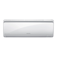
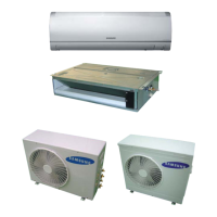
Exploded view and parts list for MH020FVEA, MH026FVEA, MH035FVEA, and MH052FVEA indoor units.
Exploded view and parts list for MH020FAEA, MH026FAEA, MH035FAEA, and MH052FAEA indoor units.
Exploded view and parts list for MH026FSEA and MH035FSEA indoor units.
Exploded view of the PSSMA Slim 1 way Cassette Panel, showing numbered components and their layout.
Exploded view and parts list for MH030FMEA, MH035FMEA, and MH052FMEA indoor units.
Exploded view of the PMSMA Mini 4 way Cassette Panel, detailing components and their numerical references.
Exploded view and parts list for MH026FJEA, MH035FJEA, and MH052FJEA indoor units.
Exploded view and parts list for NJ026LHXEA and NJ035LHXEA indoor units.
Exploded view and parts list for the MH052FUEA indoor unit.
Exploded view and parts list for AQV07/09/12/18/24PSBN indoor units.
Exploded view diagrams and parts lists for outdoor units, covering various models.
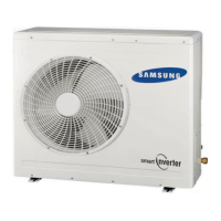
Exploded view and parts list for RJ040F2HXEA and RJ050F2HXEA outdoor units.
Exploded view and parts list for RJ060F3HXEA, RJ070F4HXEA, and RJ080F4HXEA outdoor units.
Exploded view and parts list for the RJ100F5HXEA outdoor unit.
Exploded view and parts list for the Assy Control Out of RJ040F2HXEA/RJ050F2HXEA models.
Exploded view and parts list for the Assy Control Out of RJ060F3HXEA, RJ070F4HXEA, and RJ080F4HXEA models.
Diagram of the indoor unit's main PCB, showing numbered components and their functions.
Detailed labeling of components on the MH****FNEA indoor unit's main PCB, indicating power, sensors, and communication points.
Diagram of the outdoor unit's main PCB for RJ040F2HXEA/RJ050F2HXEA, showing component connections and labels.
Wiring diagram for indoor units, illustrating connections between components like display, sensors, and power.
Specific wiring diagram for MH****FNEA indoor units, showing connections for SMPS, display, sensors, and motors.
Wiring diagram for outdoor units, detailing connections for RJ040F2HXEA/RJ050F2HXEA models.
Schematic diagrams for indoor units, illustrating the electronic circuits for various functions like display, sensors, and communication.
Detailed schematic diagrams for MH****FNEA and MH****FVEA indoor units, showing circuit layouts.
Schematic diagram of the outdoor unit's main PCB for RJ040F2HXEA/RJ050F2HXEA, detailing circuit components and connections.
Guidelines for selecting an optimal installation area for the air conditioner, considering ventilation and environmental factors.
Specific criteria for choosing the installation location for the indoor unit, ensuring proper airflow and avoiding heat sources.
Criteria for selecting the installation location for the outdoor unit, ensuring good ventilation, protection from elements, and noise considerations.
Guidelines for optimal use of the remote control, ensuring signal clarity and avoiding interference from sunlight or obstacles.
Procedure for connecting refrigerant pipes and purging air from the system using a vacuum pump for proper operation.
Instructions for refilling refrigerant into the air conditioner after installation or leakages, detailing the process and pressure checks.
Guidelines for adjusting refrigerant quantity based on connection pipe length and installation conditions.
Specifications for flare nut fixing torque (liquid and gas sides) to ensure proper connection and prevent leaks.
Step-by-step procedure for 'pump down' operation, essential for evaporator replacement or unit relocation.
Guide to understanding the structure and components of indoor unit model names, including product type, capacity, and version.
Guide to understanding the structure of outdoor unit model names, covering product type, capacity, chassis, and rating voltage.
Cycle diagrams illustrating the refrigerant flow for various outdoor units (RJ040F2HXEA, RJ050F2HXEA).
Table showing the conversion between different units of power (W, cal/s, kcal/h, Btu/h, HP, kg.m/s, lb.m/s) for capacity reference.
Definitions of common technical terms used in the manual, such as COMP, BLOWER, FAN, and ASS'Y.
Frequently asked questions and answers regarding common non-trouble issues like weak cooling, operation problems, and smells.
Explanation of the air supplier's role in providing fresh air and maintaining a clean indoor environment.
Benefits of air circulation, filtration, and environmental control provided by the air supplier for user comfort.
Key factors influencing human body freshness: air circulation, heat emission, and environmental conditions like temperature and humidity.
List of GSPN web portal links for different regions, providing access to service information and support resources.
| Brand | Samsung |
|---|---|
| Model | MH052FVEA |
| Category | Air Conditioner |
| Language | English |