Do you have a question about the Samsung MH052FNCA and is the answer not in the manual?
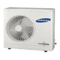
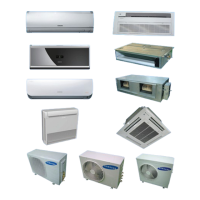
Highlights the series' ability to deliver comfort to multiple rooms with a single outdoor unit.
Details energy-saving aspects like DC inverter, BLDC compressor, and smart inverter control.
Covers features like non-polarity and auto-addressing for easy setup.
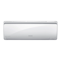
Focuses on compact design, quiet operation, and eco-friendly refrigerant.
Guidelines for safely installing the indoor and outdoor units, including site requirements and electrical safety.
Specifies requirements for power connection, circuit breakers, and avoiding hazards.
Advises on safe operational practices, avoiding liquids, and keeping the unit clear.
Instructions on safely disposing of the air conditioner and its components.
General precautions, including handling, supervision of children, and current measurement standards.
Details the key benefits and characteristics of the Free Joint Multi Inverter Series.
Provides detailed technical specifications for indoor units like MH026FNCA and MH035FNCA.
Lists technical specifications for indoor unit MH052FNCA.
Details specifications for indoor units MH026FECA, MH035FECA, and MH052FECA.
Lists specifications for indoor units NJ0261HXCA and NJ0351HXCA.
Details specifications for indoor units NJ030MHXCA, NJ035MHXCA, and NJ052MHXCA.
Provides technical specifications for outdoor units MH050FXCA2A and MH080FXCA4A.
Lists accessories and their codes for indoor units like MH✳✳✳FNCA.
Lists accessories and their codes for indoor units like MH✳✳✳FECA.
Lists accessories for indoor units MH✳✳✳FECA, including cable ties and drain pipe holders.
Lists accessories for indoor units NJ✳✳✳1HXCA, including pattern sheets and insulation.
Lists accessories for indoor units NJ✳✳✳MHXCA, including pad-install and safety nets.
Lists accessories for outdoor units MH050FXCA2A and MH080FXCA4A.
Details accessories for the transmitter unit, including cables and manuals.
Explains error codes and their corresponding indicators for indoor units (MH✳✳✳FNCA).
Details error conditions and LED indications for indoor units (MH✳✳✳FECA).
Continues error code explanations for indoor units (MH✳✳✳FECA).
Lists error codes and symptoms for indoor units NJ✳✳✳1HXCA/NJ✳✳✳MHXCA.
Lists error codes and explanations for outdoor unit PCB displays.
Continues error code explanations for outdoor units, including compressor and sensor errors.
Provides a step-by-step guide to setting options using the remote controller.
Lists option codes for various models and external static pressures.
Lists essential tools required for disassembly and reassembly procedures.
Step-by-step guide for disassembling the front grille and related components of the indoor unit.
Details steps for removing control boards and drain trays from the indoor unit.
Explains how to detach the heat exchanger and fan motor assembly from the indoor unit.
Procedure for disassembling the motor and blower assembly for FECA models.
Steps for disassembling the drain pan and its components for FECA indoor units.
Details on disassembling the evaporator and associated supports for FECA indoor units.
Instructions for removing filters and bracket filters for the MH052FECA indoor unit.
Steps for disassembling the blower motor and associated covers for the MH052FECA indoor unit.
Guide for disassembling the control box and upper cabinet of the outdoor unit.
Details on detaching the fan motor and its bracket from the MH050FXCA2A outdoor unit.
Steps for disassembling the heat exchanger and compressor of the MH050FXCA2A outdoor unit.
Instructions for disassembling the control out and cabinet components of the MH080FXCA4A outdoor unit.
Exploded view diagram and parts list for indoor units MH026FNCA and MH035FNCA.
Exploded view diagram for indoor unit MH052FNCA, showing component locations.
Exploded view diagram for indoor units MH026FECA and MH035FECA.
Exploded view diagram for indoor unit MH052FECA, detailing various parts.
Exploded view diagram for indoor units NJ0261HXCA and NJ0351HXCA.
Exploded view diagram of the Slim 1 Way Cassette Panel.
Exploded view diagram for Mini 4 Way Cassette Panel units.
Exploded view diagram and parts list for the MH050FXCA2A outdoor unit.
Exploded view diagram and parts list for the MH080FXCA4A outdoor unit.
Wiring diagram for indoor units of the MH✳✳✳FNCA series.
Wiring diagram for indoor units of the MH✳✳✳FECA series.
Wiring diagram for indoor units of the NJ✳✳✳1HXCA series.
Wiring diagram for indoor units of the NJ✳✳✳MHXCA series.
Wiring diagram for the MH050FXCA2A outdoor unit.
Wiring diagram for the MH080FXCA4A outdoor unit.
Schematic diagram for indoor units of the MH✳✳✳FNCA series.
Schematic diagram for indoor units of the MH✳✳✳FECA series.
Schematic diagram for indoor units of the NJ✳✳✳1HXCA series.
Schematic diagram for indoor units of the NJ✳✳✳MHXCA series.
Schematic diagram for outdoor units MH050FXCA2A and MH080FXCA4A.
Diagram of the main PCB for indoor units (MH✳✳✳FNCA), showing component locations.
Diagram of the main PCB for indoor units (MH✳✳✳FECA), labeling various components.
Diagram of the main PCB for indoor unit NJ✳✳✳1HXCA, showing connector and component details.
Diagram of the main PCB for indoor unit NJ✳✳✳MHXCA, indicating component connections.
Diagram of the sub PCB for indoor units (MH✳✳✳FNCA), showing external signals and main PCB connections.
Diagram of the main PCB for outdoor units MH050FXCA2A/MH080FXCA4A, showing component locations.
Initial checks for common operational issues and installation integrity.
Procedures for installation checks, pipe connection tests, and outdoor PCB display settings.
Details on pipe checking operation, auto-addressing mode, and display indicators.
Explains manual addressing mode and confirms indoor address assignment.
Guide to manual addressing mode switch settings and testing operations.
Troubleshooting steps for error codes displayed on indoor or outdoor LEDs, including manual address setting.
Further troubleshooting for specific error codes (E121-E163, E221-E320) related to sensors and EEPROM.
Troubleshooting for E201 error (addressing) and E190 error (pipe checking) and E202 error (communication).
Explains operation errors like E161 (simultaneous operation) and E416 (high discharge temp).
Covers operation errors E458 (fan error), E401 (freezing), E441 (cooling temp limit), E404 (heating overload), E440 (heating temp limit).
Flowchart for basic troubleshooting, checking power, wiring, and display LEDs.
Continues the troubleshooting flowchart for communication and cycle protection related errors.
Steps for checking AC line, fuses, and LED patterns on the outdoor controller.
Instructions for checking DC voltages on various points and understanding PFC function.
Guidance on checking indoor controller functions.
How to monitor sensor temperatures using the outdoor display PCB's VIEW MODE.
Method to monitor EEV step values using the outdoor display PCB's VIEW MODE.
Refers to checking and testing operations for pipe matching procedures.
Important safety precautions before handling and replacing PCB parts.
Steps for replacing faulty PCB parts, including checks and soldering tips.
Guidelines for choosing an appropriate installation location for the indoor unit.
Procedure for connecting pipes and purging air from the system for MH050FXCA2A.
Procedure for connecting pipes and purging air from the system for MH080FXCA4A.
Steps for refilling refrigerant into the MH050FXCA2A air conditioner.
Steps for refilling refrigerant into the MH080FXCA4A air conditioner.
Guidelines for adjusting refrigerant based on connection pipe length for MH050FXCA2A/MH080FXCA4A.
Specifies torque values for fixing flare nuts based on outer diameter.
Procedure for pump down operation when replacing an evaporator or relocating the unit.
Guide to understanding model name indexing for Free Joint Multi air conditioners.
Illustrates the refrigerating cycle for the MH050FXCA2A model.
Illustrates the refrigerating cycle for the MH080FXCA4A model.
Table detailing pressure and capacity marks for power/heat.
Defines common technical terms used in the manual, such as COMP, BLOWER, and FAN.
Addresses common non-trouble issues related to cooling, leakage, and smells.
Continues Q&A on smells, operation, and when the unit won't start or goes off during operation.
Addresses remote controller operation, installation, and wind screen questions.
Explains the role and effectiveness of the air supplier in providing fresh air and maintaining environment.
Discusses the four factors influencing air supplier effectiveness: humidity, temperature, air stream, and cleanness.
| Cooling Capacity | 5.2 kW |
|---|---|
| Weight (Outdoor Unit) | 32 kg |
| Net Weight (Outdoor Unit) | 32 kg |
| Power Supply | 220-240V, 50Hz |
| Operating Temperature (Cooling) | 18-43 °C |