9-2Samsung Electronics
To complete the installation, perform the following checks and tests to ensure that the air conditioner is operating
correctly.
1. Review all the following elements in the installation:
1. • Installation site strength
1. • Piping connection tightness not to leak any gas
1. • Connection wiring
1. • Heat-resistant insulation of the piping
1. • Drainage
1. • Earthing wire connection
1. • Setting number of the indoor unit installed (Outdoor unit SW)
1. • Addressing mode (AUTO or MANUAL)
1. • Address number on each indoor unit (Manual addressing mode)
1. • Correct operation for pipe checking connection (follow the step below)
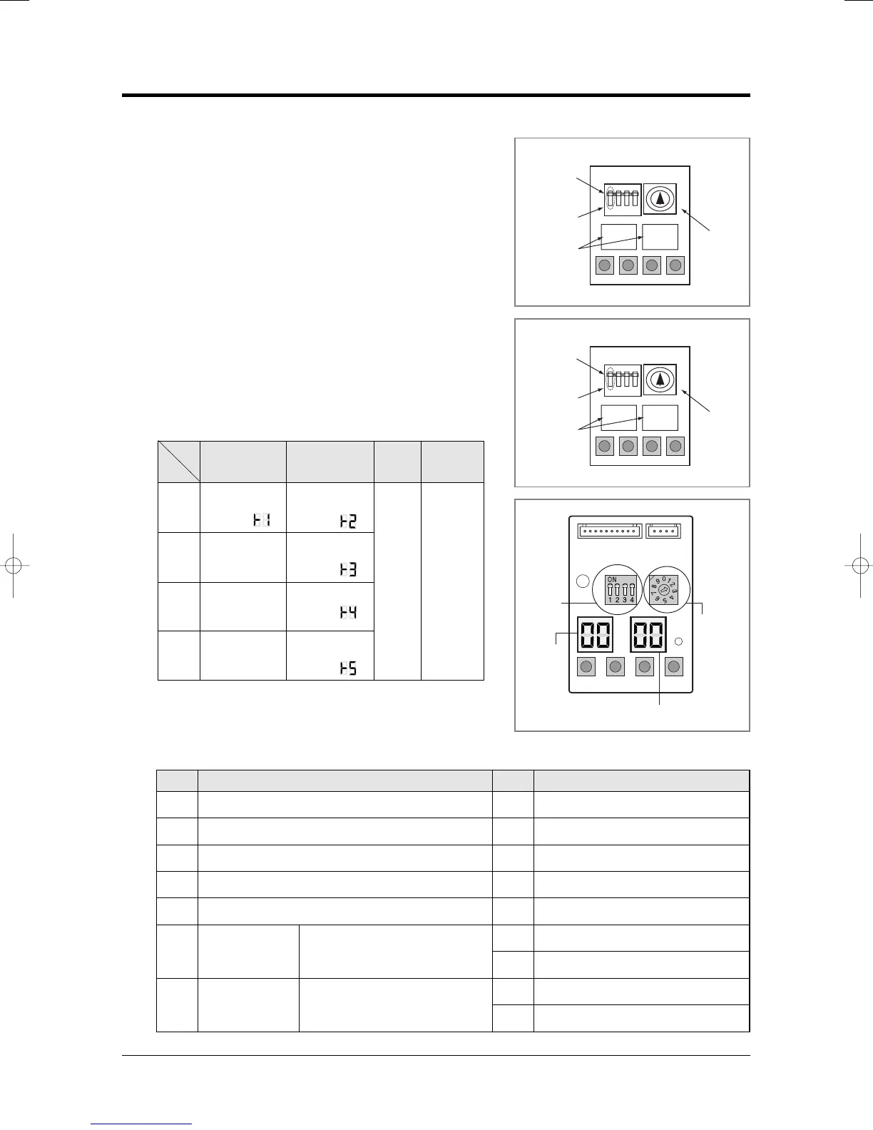
2. ■ Key Options of PCB Display
2. ■ - K1 : Test button - K2 : Function button
2. ■ - K3 : Reset button - K4 : View mode change button
2. ■ K4 View mode Display changes
9-2 Checking and Testing operations
Number of
indoor unit
Number of
indoor unit
MANUAL
Addressing
AUTO
Addressing
7 segment
LED
2digits x 2
Push
Key
K1
K2 K3 K4
1
Heat mode
Try-run
(Display: )
Reset
View mode
change
2-
3
-
4-
Refrigerant
Charging
(Display: )
Cool mode
Try-run
(Display: )
Pump down
(Display: )
Checking of
pipe connection
(Display: )
K 1 K 2 K 3
(OFF)
DIS01
SW02 SW01
K 4
DIS02
Outdoor PCB Display
Indoor unit
address
View data display
Display Explanation Display ExplanationPush Push
0
1
2
3
4
5
6
7
8
9
10
11
12
13
14
15
Present Compressor Frequency
Target Compressor Frequency
Order Compressor Frequency
EEV0 current step
EEV1 current step
EEV3 current step
Fan RPM (H: high, L: low, Blank: off)
Discharge temperature
OLP temperature
Condenser temperature
Outdoor temperature
Primary current
Target Discharge temperature
Total capacity of the indoor units
Safety control code
Switch
EEV2 current step
MH040FXEA2✳/MH052FXEA2✳/
MH✳✳✳✳✳✳ Always Zero
MH040FXEA2✳/MH052FXEA2✳/
MH✳✳✳✳✳✳/MH060FXEA3A
Always Zero
<MH✳✳✳FXEA✳A>
Number of
indoor unit
AUTO
Addressing
MANUAL
Addressing
7 segment
LED
2digits x 2
<MH✳✳✳FXEA✳>