Transmitter Installation (Optional) (Continued)
I
NSTALLING THE
O
UTDOOR
U
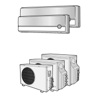
NIT
E-14
Accessories (Transmitter)
Accessories (Outdoor Unit)
2 Attach the transmitter PCB to the case in the control box in the outdoor
unit, then connect the power and the communication cable between the
transmitter and the outdoor unit; refer to the figure of page 15.
1 Fix the case with bolts on the control box in the outdoor unit.
(See the picture)
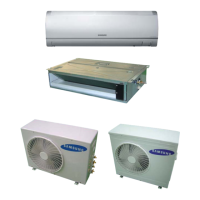
3 If you install a transmitter to an outdoor unit, every indoor unit which is
connected to an outdoor unit can be controlled simultaneously.
4 Each outdoor unit connected to the same centralized controller has its
own transmitter.
Case Cable-tie
Installation Manual
Transmitter Transmitter power
cable
Transmitter
communication cable
Fix the case with bolts
(Control Box in the outdoor unit)
7seg. LED
Display side
Terminal
side
Bolts spec.
M4
Transmitter
Flare Bolt
(Nut 1/2”, Bolt 3/8”)
Transmitter power
cable
3-wire
Power Cable
(option)
Rubber Leg
2-wire
Assembly Cable
(option)
Flare Nuts, 6.35mm
outer pipe diameter
Flare Nuts, 9.52mm
outer pipe diameter
Drain Plug
◆ MH068FXEA4 / MH080FXEA4
Energy Label
 Loading...