Do you have a question about the Samsung MM-G25 and is the answer not in the manual?
Follow safety rules to prevent electrical shock and damage.
Guidelines for safe and proper servicing procedures.
Methods to prevent damage to ESD-sensitive components.
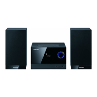
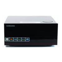
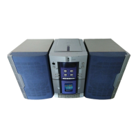
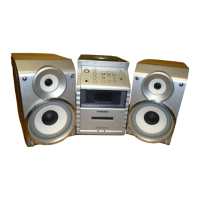
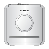
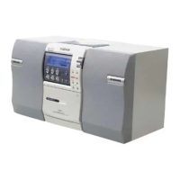
Details on the features and capabilities of the audio system.
Technical specifications including audio, power, and dimensions.
Comparative analysis of specifications across different models.
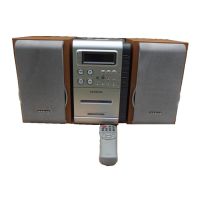
List of accessories included with the product.
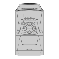
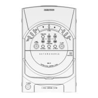
Step-by-step guide for disassembling and reassembling the unit.
Diagnostic flowcharts for identifying issues based on error modes.
Procedures for initializing and updating firmware.
Instructions for setting the region code using the remote control.
Diagrams showing the assembly of the product's components.
Details and parts list for the speaker system.
Comprehensive list of electrical components with part numbers.
Overview of connections between different PCBs.
Top view layout of the front PCB with component placements.
Bottom view layout of the front PCB with component placements.
Top view layout of the tape PCB with component placements.
Bottom view layout of the tape PCB with component placements.
Top view layout of the main PCB with component placements.
Bottom view layout of the main PCB with component placements.
Top view layout of the MPEG PCB with component placements.
Bottom view layout of the MPEG PCB with component placements.
Block diagram illustrating the system's overall architecture.
Schematic diagram for the front section of the unit.
Schematic diagram for the tape deck section.
Schematic diagram for the main control section.
Schematic diagram for the MPEG processing section.
Schematic diagram for the Switched-Mode Power Supply.
| Equalizer | Yes |
|---|---|
| RMS rated power | 120 W |
| Audio output channels | 2.0 channels |
| Audio formats supported | MP3, WMA |
| Supported radio bands | FM |
| Preset stations quantity | 30 |
| Optical disc player type | DVD player |
| Weight | 5600 g |
| Dimensions (WxDxH) | 260 x 170 x 134 mm |
| USB version | 2.0 |
| USB ports quantity | 1 |
| Package weight | 6800 g |