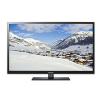
Do you have a question about the Samsung PS42C96HDX/XEC and is the answer not in the manual?
Lists main sections of the service manual.
General steps for taking apart and reassembling the unit.
Instructions for removing the rear cover assembly.
Steps for detaching the main PCB and associated components.
Procedure for removing the EMI filter from the AC line.
Guide for detaching the bracket connected to the PCB.
Steps for removing various bracket assemblies.
Instructions for removing the AV board.
Procedure for removing the wall bracket assembly.
Steps for detaching the speaker assembly.
Guide for removing the power and IR board.
Procedure for removing the SMPS (Switched-Mode Power Supply).
Steps for removing the logic main board module.
Procedure for removing the X main board module.
Steps for removing the Y main board module.
Procedure for removing the address buffer board module.
Instructions for removing panel mounting brackets.
Steps for detaching the function PCB.
Visual breakdown of parts for the 42-inch model.
Visual breakdown of parts for the 50-inch model.
List of service parts for the 42-inch model with codes.
List of service parts for the 50-inch model with codes.
Guidelines for safe handling and installation of the product.
Highlights critical safety features and parts requiring attention.
Specific safety instructions for service personnel during repairs.
Procedures to prevent damage from electrostatic discharge.
Guidelines for safe and proper installation of the television.
Detailed technical specifications of the PDP television models.
Comparison and analysis of product specifications across models.
Lists supplied and optional accessories for the TV.
Explanation of the television's circuit blocks and their functions.
Schematic of the power supply unit (SMPS) and related circuits.
Schematic diagram for the audio processing circuitry.
Schematics for HDMI, PC, and DVI input/output connections.
Schematics for SCART, AV, S-Video, and other input/output jacks.
Schematic diagram for the microcontroller (MICOM) units.
Schematic for the video scaler IC.
Schematics for the DDR memory and tuner circuits.
Schematic for DTV reset functions and AV output.
Schematics for DTV memory and STi5105 chipset.
Schematics for PCMCIA interface and STi5105 chipset.
Initial steps to diagnose common television problems.
Diagnostic procedures categorized by specific error symptoms.
Troubleshooting steps for when the TV does not turn on.
Diagnosing issues with the unit repeatedly powering on/off.
Troubleshooting steps for no video output with normal audio.
Troubleshooting steps for no audio output with normal video.
Troubleshooting steps for blank or abnormal video display.
Specific diagnostic procedures for the SMPS.
Troubleshooting specific to the drive boards (Y-MAIN, X-MAIN, Logic).
Overview table of common board-related troubleshooting issues.
Flowcharts for diagnosing abnormal display conditions.
Step-by-step diagnosis for a completely blank screen.
Diagnosing issues with distorted or incorrect images.
Troubleshooting for missing horizontal lines (Sustain Open).
Troubleshooting for linked horizontal lines (Sustain Short).
Diagnosing issues related to address signal open or short circuits.
Common visual faults and their corresponding fixes.
Guides for troubleshooting specific assemblies like SMPS, main boards, etc.
Procedures for adjusting TV settings after component replacement.
General instructions for performing after-sales service adjustments.
Steps to enter and navigate the TV's service mode.
Details of factory settings and options for adjustment.
Specific procedures for service adjustments like White Balance.
Steps to perform white balance calibration using specific patterns.
Guide for adjusting white balance controls for image quality.
Detailed steps for performing image quality adjustments.
Required calibration steps after replacing major assemblies.
Procedures for adjusting SMPS and PDP panel voltages.
Adjustments for Y-signal response time and frequency controls.
Procedures for upgrading firmware or software.
Guide for updating the flash ROM using an RS-232C cable.
Instructions for verifying the installed software version.
High-level block diagram showing major connections.
Detailed pin-out information for various connectors.
Description of connector functions and their locations.
| Screen Size | 42 inches |
|---|---|
| Display Type | Plasma |
| Resolution | 1024 x 768 |
| Aspect Ratio | 16:9 |
| Brightness | 1500 cd/m² |
| HDMI Ports | 3 |
| Component Video Input | 2 |
| Composite Video Input | 1 |
| Audio Output | 10W x 2 |
| Response Time | 0.001 ms |
| USB Ports | 1 |
| Viewing Angle | 175°/175° |






 Loading...