Do you have a question about the Samsung rf221 series and is the answer not in the manual?
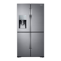
| Cooling System | Twin Cooling Plus |
|---|---|
| Ice Maker | Yes |
| Energy Star Certified | Yes |
| Water Dispenser | Yes |
| Energy Star Compliant | Yes |
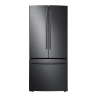
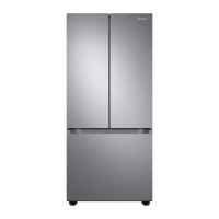
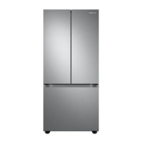
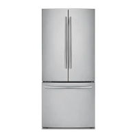
| Type | French Door |
| Fresh Food Capacity | 15.1 cu. ft. |
| Color | Stainless Steel |
| Width | 35 3/4" |
Guides on activating and using Force Mode for compressor and fan operation.
Details on activating Diagnostic Mode and interpreting load condition displays.
Explanation of Demo Mode where no heating or cooling elements will work.
Lists resistance, wattage, and voltage for various refrigerator components.
Details on DC fan motor operation, testing, and troubleshooting common issues.
Explains the process of ice production after water fill and temperature checks.
Procedure for testing the Ice Maker's harvest function and heater operation.
Describes how the ice maker influences freezer temperature settings.
Provides temperature, resistance, and voltage data for refrigerator sensors.
Lists LED error codes, corresponding items, trouble contents, and diagnostic methods.
Details AC load connections for heaters, ice duct, and common lines.
Identifies BLDC motor and door switch connections on the main PCB.
Lists sensor connections including humidity, freezer, and ambient sensors.
Shows wiring for AC loads like defrost heaters and French heater.
Details wiring for BLDC motors, door switches, and fan motors.
Illustrates sensor wiring for humidity, freezer, and ambient sensors.
Explains compressor protection functions and corresponding LED blinking patterns.
Details LED blinking frequencies linked to specific compressor protection functions.