EasyManua.ls Logo

Samsung RS25H50 User Manual

Samsung RS25H50
8 pages
To Next Page IconTo Next Page
Page #1 background imageLoading...
Page #1 background image
Fast Track Troubleshooting
Model:
RS25H50
Publication # MY RS25H50 Production Date 05/13/2014 Updated 7/21/2014
IMPORTANT SAFETY NOTICE “For Technicians Only” This service data
sheet is intended for use by persons having electrical, electronic, and mechanical experience
and knowledge at a level generally considered acceptable in the appliance repair trade. Any
attempt to repair a major appliance may result in personal injury and property damage. The
manufacturer or seller cannot be responsible, nor assume any liability for injury or damage of
any kind arising from the use of this data sheet.
Bulletins:
Support Information:
HELP: 1-888-751-4086 (Tech Sup. ASC/SSD)
1-866-894-0637 (Tech Sup. - FE/ME)
GSPN: http://service.samsungportal.com/EP/web/portal/jsp/EP_Default1.jsp
PLUS ONE: http://my.plus1solutions.net/clientPortals/samsung
Force Mode:
• Press Energy Saver and Fridge
buttons simultaneously for 8 seconds
to get in the ready mode for a forced
operation. (The below picture)
• The display panel will return to normal
after 15 seconds in the ready mode.
• In the ready mode, press any button
once to start a compressor on
operation, twice for defrost cycle for
the freezer, and finally three times for
cancellation of this function
• Another way to cancel this function is
to simply plug out the power cord and
plug it back in.
1) Compressor on (Pull Down) mode
1-1) In the ready mode, press any button once - then the
buzzer will beep (ON for 1/2 second and OFF for 1/2 second)
until this mode is cancelled.
1-2) In this compressor on mode, the compressor will start
immediately (No 7 minute delay) and if the system is in the
defrost cycle, it will be cancelled right away.
2) Freezer-Defrost operation
2-1) In the ready mode, press any button twice to begin the
defrost cycle for the Freezer-Defrost.
2-2) The beep sound continues for 3 second at the beginning,
then ON for 3/4 seconds and OFF for 1/4 second until this
mode ceases.
2-3) After this operation, the system will come back to normal
operation.
3) Cancellation
3-1) In the F-Defrost mode, press any button again to return
to a normal operation.
3-2) Or, simply unplug the power cord, then plug it again to
return to a normal operation.
1 For units produced June 2014 and later, to select for the
Cooling Off mode, press the top left, middle left, and top right
buttons simultaneously for 5 seconds until a “ding-dong” sound
is heard.
2 To cancel this mode, press the same buttons again for 5
seconds until a “ding-dong” sound is heard.
To select this function, press Lighting
and Energy Saver buttons
simultaneously for 8 seconds with an
audible tone.
In the self diagnostic mode, only
corresponding LED segments will be
illuminated (see the check list below)
After a 30 second illumination of error
signal, the system will return to the
normal operation.
NO Error
LED Display
ICE MAKER
SENSOR
Right - LED
ON
MAIN↔PAN
EL
COMMUNICA
TION ERROR
Right - LED
ON
COMP ERROR
Right - LED
ON
REFRIGERATO
R
SENSOR
Right - LED
ON
Damper
Heater Error
Right - LED
ON
ICE MAKER
FUNCTION
ERROR
Right - LED
ON
EXIT-SENSOR
Left - LED ON
FREEZER
SENSOR
Left - LED ON
FREEZER
DEFROST
SENSOR
Left - LED ON
FREEZER FAN
ERROR
Left - LED ON
CONDENSER
FAN ERROR
Left - LED ON
FREEZER
DEFROST
ERROR
Left - LED ON
Self-Diagnostics Function
Cooling Off Function (Demo Mode)
1) In the normal operation, press Lighting and Energy Saver
buttons simultaneously for 6 seconds, then the display
panel will blink for 2 seconds.
2) Press Fridge Temp. button to get into this check mode
with an audible tone.
3) Each illuminating LED segment stands for the component
which has an output signal from the control board.
4) This mode will terminate automatically after 30 seconds.
Load Operation Check Function
1 To select for the Cooling Off mode, press the top left and
middle left buttons simultaneously for 5 seconds until a “ding-
dong” sound is heard.
Question and Answer IconNeed help?

Do you have a question about the Samsung RS25H50 and is the answer not in the manual?
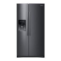
Samsung RS25H50 Specifications

General IconGeneral
BrandSamsung
ModelRS25H50
CategoryRefrigerator
LanguageEnglish

Summary

Fast Track Troubleshooting

Self-Diagnostics Function

Initiate diagnostic mode by pressing buttons to check sensors and components.

Force Mode Operation

Activate compressor or defrost cycles for testing via button presses.

Cooling Off Mode Activation

Select and cancel cooling off mode using button combinations.

Load Operation Check Function

Verify component output signals using illuminated LED segments.

DC Fan Motor Operation and Testing

Testing Fan Circuit Voltage

Procedure to check DC voltage to the fan motor for proper operation.

Fan Blade and Evaporator Ice Blockage

Troubleshooting steps for fan blockage due to ice or obstructions.

Ice Maker Heat Release Function

Ice Production Explanation

Details the process of ice production and harvest timing.

Heat Release I/M Test Mode

Procedure to test the ice maker harvest and heater functions.

Freezer Temperature Control via Ice Maker

Freezer Temperature Setting Logic

How freezer temperature is managed based on ice bucket status.

Self-Diagnostic Error Items

Ice Maker Sensor Error

Details and diagnosis for ice maker sensor issues.

Main Panel Communication Error

Error related to communication between main and panel microcontrollers.

Compressor Error Diagnosis

Information on compressor faults like IPM fault or over-voltage.

Refrigerator Sensor Errors

Diagnosis for refrigerator sensor connection or failure.

Damper Heater Error

Troubleshooting damper heater issues caused by connection or wire faults.

Ice Maker Function Error

Diagnosis for ice maker failures like ice-ejector issues.

Ambient Air Sensor Error

Checks for ambient air sensor connection, wire cuts, or failure.

Freezer Sensor Errors

Diagnosis for freezer sensor connection or room sensor failure.

Freezer Defrost Sensor Error

Troubleshooting freezer evaporator defrost sensor issues.

Freezer Fan Error

Addresses freezer fan motor operation and feedback line failures.

Condenser Fan Error

Diagnosis for condenser fan motor operation or wire issues.

Freezer Defrost Error

Identifies errors related to freezer defrost mode time limits.

Main PBA Block Diagram

AC Input and Load Components

Overview of AC input filtering and connected AC loads.

DC Control Circuits

Details on 13V DC load distribution and control circuits.

Sensor Input and Control

Wiring and sensing for various components like sensors and switches.

Panel PBA Interface

Connection and communication interface with the panel board.

Inverter PBA Block Diagram

Power Supply and SMPS Circuit

Description of the SMPS circuit providing power to the inverter.

Inverter Control Circuits

Overview of compressor control and IPM circuits.

MCU and Protection Circuits

Role of MCU, protection, and feedback circuits.

Main Board Connector Layout

CN75 Connector Details

Pinout and function for CN75 connector on the main board.

CN90 Connector Details

Pinout and function for CN90 connector on the main board.

CN30 Connector Details

Pinout and function for CN30 connector on the main board.

CN50 Connector Details

Pinout and function for CN50 connector on the main board.

Inverter Board Connector Layout

CN103 Connector Details

Pinout and function for CN103 connector on the inverter board.

LED Blinking Frequency Indicators

Normal Operation Blinking

LED blinking pattern during normal operation.

Protection Function Blinking

LED blinking patterns indicating various protection modes.

Wiring Diagram - Main Board Connections

Door Switch Connections

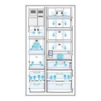
Wiring for refrigerator and freezer door switches.

Water and Ice System Wiring

Connections for water/ice solenoids and switches.

Heater and Motor Wiring

Wiring for various heaters and motors like Auger, Eject, Fan.

Sensor and Thermistor Wiring

Connections for temperature sensors and thermistors.

Ice Maker Kit Wiring

Wiring diagram for the ice maker kit components.

Inverter Board Component Functions

PCB Power Supply Function

Description of the power supply circuit on the inverter board.

Inverter Control Circuit Function

Role of the inverter in compressor control.

COMP Driving/Feedback Circuit

Function of the COMP driving and feedback circuitry.

Bootstrap Charger Function

Description of the bootstrap charger circuit.

Current Pickup Circuit Function

Explanation of the current sensing and PWM duty control.

IPM and Micom Components

Functions of the IPM and Micom controllers.

Related product manuals