57
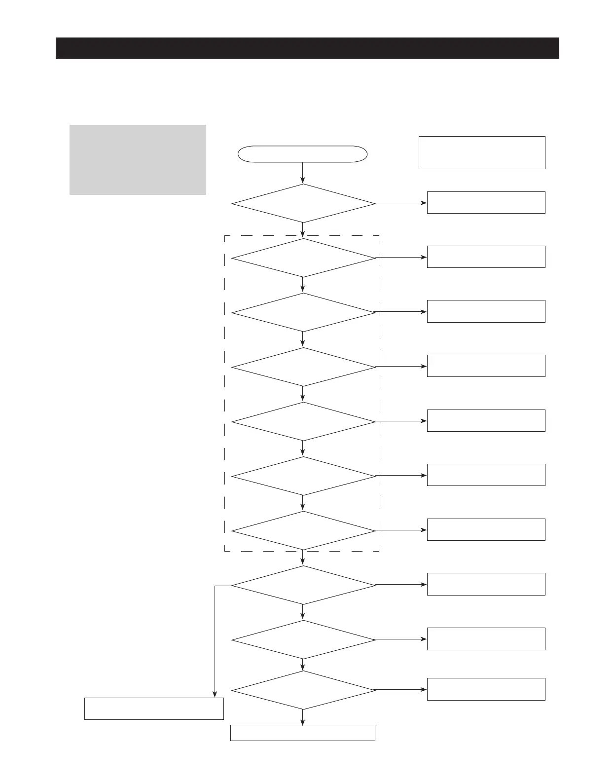
TROUBLESHOOTING
;\IZ\
Caution
There is AC 110~127V or DC
156~180V at the MAIN PCB
Power Circuit. So, be cautious
when repairing the unit or
measuring values.
Normal (Check again)
Yes
The unit is plugged in?
Yes
110~127V is applied
at MAIN PCB
CN70 terminals?
No
MAIN PCB Fuse is blown?
Yes
DC 156~180V is applied
at BD1+/- terminals?
Yes
DC 6.2V is applied at
TOP S/W 3-12(BETTER),
2-8(GOOD) ?
Yes
12V is applied at
CE109 terminals?
Yes
5V is applied at
CE113 terminals?
Yes
Panel PCB operates
normally?
Loads such as Relay
operate normally?
Is there PCB Short
or breakage?
Yes
No
Plug in the unit
No
Check the wire connections
No
1) Replace Fuse (AC 250V 2.0A)
2) Replace PCB ASS'Y
Yes
Replace PCB ASS'Y
No
Replace PCB ASS'Y
No
Replace PCB ASS'Y
No
Replace PCB ASS'Y
No
1) Check the wire connections
2) Replace Panel PCB
- Check the connection of Door Panel
PCB
No
1) Check Lead Wire connections
2) Replace Relay or PCB ASS'Y
1) Do Re-soldering
2) Replace PCB MAIN
No
Yes
- When checking the MAIN PCB, refer
to the Operation descriptions and
the "Reference" section.
4-2-4-2. Area that is Rated input voltage 110~127V.