Do you have a question about the Samsung SCM-6700 and is the answer not in the manual?
Essential safety measures to follow during servicing and operation.
Procedure for testing electrical leakage current.
Procedure for checking insulation resistance.
Guidelines and precautions for performing service procedures safely.
Measures to protect components sensitive to static discharge.
Safety measures specific to laser product handling and warnings.
Overall technical specs and amplifier section details.
Technical details for FM, MW, and LW tuner bands.
Technical details for cassette and CD player sections.
Instructions for disassembling cabinet parts and turntable.
Steps to remove CD deck, front PCB, cassette deck, and door.
Procedures for removing the cabinet bottom and main PCB.
Detailed instructions for disassembling the CD pack mechanism.
Steps for disassembling the CD deck components.
Alignment and adjustment procedures for the tuner section.
Procedures for adjusting FM THD, search level, and stereo.
Test equipment and procedures for AM tuner alignment.
Alignment and adjustment procedures for the cassette deck.
Procedure for adjusting the recording bias.
Procedures for CD focus, tracking, and E/F balance adjustments.
Procedures for adjusting CD focus bias, gain, and tracking.
Troubleshooting steps for power malfunctions and no-sound issues in FM/AM.
Troubleshooting steps for power-related issues.
Steps to diagnose and fix FM no-sound problems.
Steps to diagnose and fix AM no-sound problems.
Troubleshooting guide for tape playback issues.
Steps to resolve audio output malfunctions.
Troubleshooting specific to CD player functions.
Steps to fix issues with disc rotation.
Troubleshooting steps for CD audio output problems.
Exploded view and parts list for the cassette mechanism.
Exploded view and parts list for the main unit assembly.
Parts list for the CD pack assembly.
Parts list for the CD deck assembly.
Parts list for the turntable assembly.
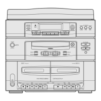
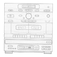
High-level functional overview of the unit's main architecture.
Block diagram for the CD playback system.
Internal schematic diagrams for integrated circuits and transistors.
Pinout and function details for key microcontrollers and DSPs.
Internal diagrams for CD-related ICs like NIC9270 and NIC9258.
Pinout and function list for the NIC9220 ASSP.
Pinout and function list for the NIC9282 DSP.
Component layout diagrams for the CD PCB, top and bottom views.
Component layout diagram for the top view of the CD PCB.
Component layout diagram for the bottom view of the CD PCB.
Overall schematic diagram for the main unit's electrical circuits.
Schematic diagram for the CD playback section's electrical circuits.
| Brand | Samsung |
|---|---|
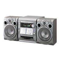
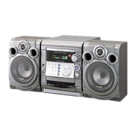
| Model | SCM-6700 |
| Category | Stereo System |
| Language | English |