Step
Item
Connection SSG.FREQ.
FREQ. Setting
Adjust. Point
Remark
Maximum
output
Maximum output
Maximum output
1
Intermediate
frequency (IF)
adjustment
AM frequency
coverage
adjustment
Figure 4-5
Figure 4-4
Connect DC
voltmeter to TCON1
and GND(TP1)
522 KHZ
522 KHZ IT 2
OT 1
OCT 2
OL 1
OCT 1
9V
0.9V
522 KHZ
594 KHZ
1404 KHZ
1611 KHZ
594 KHZ
1404 KHZ
Figure 4-5
_
_
_
Repeat step 2 and 3 serveral times
Repeat step 5 and 6 several times
AM tracking
adjustment
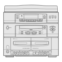
Figure 4-4 AM Frequecny Coverage Adjustment
Figure 4-5 AM Tracking Adjustment
SET
TP2
DC Voltmeter
Input
TP1
AM Signal
Generator
Test Loop
Antenna
AM
Loop Antenna
Jack
Speaker
terminal
GND
Oscilloscope
VTVM
IN
OUT
SET
60 cm
Samsung Electronics4-2
Alignment and Adjustments
2
3
4
5
6
7
4-1-1 Test Equipment
1. AM Standard Signal Generator (S.S.G) : 400Hz, 30% MOD
2. Oscilloscope
3. VTVM
4. Frequency counter
5. Loop antenna
6. Dummy load (4½)
7. DC voltmeter
4-1-2 Pre-Adjustment
1. Check the source voltage.
2. Set function and band switches to the band to be aligned.
3. Set the equalizer, volume and balance controls to mid position.
4-1-3 AM Adjustment
 Loading...