Do you have a question about the Samsung SR-65KTC and is the answer not in the manual?
| Brand | Samsung |
|---|---|
| Model | SR-65KTC |
| Category | Refrigerator |
| Language | English |
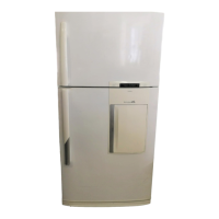
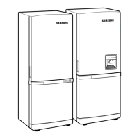
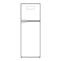
Details refrigerator models, capacities, dimensions, and weights.
Specifies electrical requirements and ratings for different models.
Explains symbols and general warnings for safe operation and maintenance.
Defines symbols used for prohibitions, cautions, and mandatory actions.
Lists standard specifications for refrigeration components like compressor, cooler, condenser.
Details temperature control settings for freezer and refrigerator compartments.
Specifies defrost cycle times and pause times for the refrigerator.
Provides the wiring diagram for the electronic control system of specific models.
Shows the wiring diagram for the semi-basic control system of other models.
Illustrates the path of cool air within the refrigerator and freezer compartments.
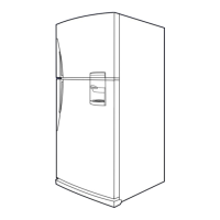
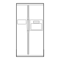
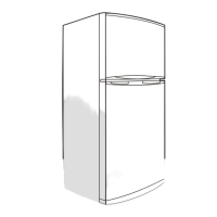
Presents dimensional data and specifications for the external structure of the refrigerator.
Identifies internal parts and provides basic disassembly steps.
Details the display design and functions of the electronic temperature control system.
Explains the temperature control functions and defrosting for semi-electronic models.
Explains the operational principles of the power supply, oscillator, and reset circuits.
Describes the power and departure circuit operations for semi-electromagnetic models.
Provides a flowchart for diagnosing and repairing power-related issues in specific models.
Outlines troubleshooting steps for sensor failures detected during self-diagnosis.
Details troubleshooting for continuous alarming issues, including door switches.
Offers diagnostic procedures for when the refrigerator's fans fail to operate.
Flowchart for diagnosing power issues in SEMI electronic mode models.
Exploded view and parts list for the freezer compartment of specific models.
Exploded view and parts list for the freezer compartment of other models.
Exploded view and parts list for the refrigerator compartment of specific models.
Exploded view and parts list for the refrigerator compartment of other models.
Lists components related to the cabinet and unit assembly for specific models.
Lists components related to the cabinet and unit assembly for other models.
Details parts associated with the refrigerator doors.
Step-by-step guide for disassembling and assembling refrigerator doors.
Instructions for replacing the lamp in the freezer door.
Instructions for replacing the lamp in the refrigerator door.
Guide for disassembling the cooling components within the refrigerator.
Steps for disassembling the cooling components within the freezer compartment.
Method for disassembling the DID door.
Explains the assembly process for the main unit components.
Details the assembly of the electric box.
Details the assembly of the electric box.
Illustrates how to pack the doors and cabinet for shipping.
Shows examples of front and back side packing for the refrigerator.
Demonstrates an example of complete and secure packing for the appliance.
Describes the specifications and features of 3-terminal 1A positive voltage regulators.
Details the specifications and function of the KA7533 reset IC.