EasyManua.ls Logo

Samsung VP-D371 User Manual

Samsung VP-D371
212 pages
To Next Page IconTo Next Page
Page #1 background imageLoading...
Page #1 background image
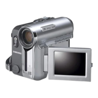
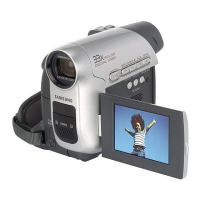
DIGITAL VIDEO CAMCORDER
Chassis : Dragon III
BASIC : VP-D371
Application Models
: VP-D371(i), VP-D371W(i),
VP-D372WH(i), VP-D375W(i),
VP-D975W(i)
Application Area
:
XEF, XEU, XEG, XET, XEV, XEC, XSA, CDM,
XST, XEO, XEH, XEP, XEE, EAP, EUR, XEN,
HACO, TAW, TIT, COL, SEO, XSS, SED, XSH,
XSG, FES, XTL, CHN, ZAM, STS, SMR, XFA,
ITN, KNT, XSE, FPT, RAD, AFR, AND, UMG
MEA, SEA
SERVICE
Œ Shooting & compact Design
´ Direct Print System : PictBridge
TM
ˇ LED Light
¨ High quality MPEG4
ˆ Still image Interpolation
Ø Real Wide mode (16:9)/WIDE LCD
34X ZOOM (Normal model)
26X ZOOM (Mega model)
USB 2.0 Streaming
Manual
DIGITAL VIDEO CAMCORDER Merit & Character regarding Product
SERVICE MANUAL VP-D371(i)/D371W(i)/D372WH(i)/D375W(i)/D975W(i)
ELECTRONICS
© Samsung Electronics Co., Ltd. FEB. 2007
Printed in Korea
AD82-00183A
This Service Manual is a property of Samsung Electronics Co .,Ltd.
Any unauthorized use of Manual can be punished under applicable
International and/or domestic law.
Area Web Site
North America URL ; http://service.samsungportal.com
Latin America URL ; http://latin.samsungportal.com
CIS URL ; http://cis.samsungportal.com
Europe URL ; http://europe.samsungportal.com
China URL ; http://china.samsungportal.com
Asia URL ; http://asia.samsungportal.com
Mideast & Africa URL ; http://mea.samsungportal.com
If you want to know additional information which is not included on this
Service Manual, Please refer to the SKP(Samsung Knowledge Portal)
web site.

Table of Contents

Question and Answer IconNeed help?

Do you have a question about the Samsung VP-D371 and is the answer not in the manual?

Samsung VP-D371 Specifications

General IconGeneral
Filter size27 mm
Digital zoom1200 x
Optical zoom34 x
Image stabilizerYes
Focal length range2.3 - 75.9 mm
Focal length (35mm film equivalent)35.3 - 1164.9 mm
Total megapixels0.8 MP
Optical sensor size1/6 \
Optical sensor resolution800000 pixels
Display diagonal2.7 \
Display resolution112000 pixels
Camcorder tape typeMini-DV
Camera shutter speed1/60 - 1/10000 s
Minimum illumination0 lx
DV port-
PictBridgeNo
Product colorBlack
Weight and Dimensions IconWeight and Dimensions
Depth52 mm
Width104 mm
Height93 mm
Weight410 g

Summary

1. Precautions

1-1 Safety Precaution

Guidelines for safe instrument servicing, including checks before returning to customer.

1-3 ESD Precautions

Techniques to reduce component damage from static electricity for sensitive devices.

3. Alignment and Adjustments

3-1 VCR Adjustment

Procedure for adjusting the Video Recording (VCR) system parameters for optimal performance.

3-2 Camera Adjustment

Steps for adjusting camera system parameters like zoom, focus, and white balance.

3-3 Deck Adjustment

Maintenance and adjustment procedures for the tape deck mechanism.

4. Disassembly and Reassembly

4-1 Cabinet and PCB

Instructions for removing and reassembling the camcorder's cabinet and printed circuit boards.

5. Exploded View and Parts List

5-1 Ass’y Chassis

Exploded view of the camcorder chassis and list of associated parts.

5-11 Mechanical Parts (Main Chassis)

List of mechanical parts for the main chassis.

6. Electrical Parts List

P001 ASSY PCB-MAIN BOARD

Main PCB assembly part number and description.

7. Block Diagrams

7-1 All Block Diagram

Overall block diagram showing the camcorder's system architecture.

7-2 ICD01(S5C7377X) Block Diagram

Block diagram of the ICD01 (S5C7377X) chip.

7-3 IC201(GLOBALi) Block Diagram

Block diagram of the IC201 (GLOBALi) chip.

7-4 Syscon/Servo Block Diagram

Block diagram for the system controller and servo functions.

8. Wiring Diagram

9. PCB Diagrams

9-1 Main PCB

Component and conductor side layout of the main printed circuit board.

10. Schematic Diagrams

10-1 DC/DC (Main PCB)

Schematic diagram for the DC/DC power supply on the main PCB.

12. Troubleshooting

14. Reference Information

Related product manuals