Do you have a question about the Samsung VR400PVR400PC and is the answer not in the manual?
Essential safety checks, including leakage current, antenna, high voltage, and static discharge procedures.
Warnings concerning picture tube handling, design alterations, hot chassis, and product safety notices.
Overview of adjustments, remote control usage, and test point locations for calibration.
Identifies key test points on the Main PCB for adjustment procedures.
Detailed procedures for adjusting ACE head height, tilt, azimuth, and position for optimal performance.
Instructions for head switching point adjustment and configuring NVRAM options for model specifics.
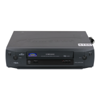
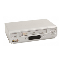
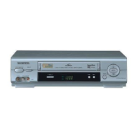
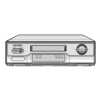
Exploded view and part identification for the VCR's cabinet and external assemblies.
Diagrams and lists detailing mechanical parts on both the top and bottom sides of the VCR deck.
Comprehensive list of electrical components categorized by functional sections like SMPS, Logic, and Audio/Video.
Diagram illustrating functional blocks on the VCR's Main Printed Circuit Board.
Circuit diagrams detailing the Switch Mode Power Supply and power distribution systems.
Circuit diagrams for logic, audio/video processing, input/output, and display sections.
| Brand | Samsung |
|---|---|
| Model | VR400PVR400PC |
| Recording Formats | VHS |
| Number of Heads | 4 |
| Tuner | Yes |
| Type | VCR |
| Playable Formats | VHS |
| Inputs | Composite video, Audio (RCA) |
| Outputs | Composite video, Audio (RCA) |
| Remote Control | Yes |