Alignment and Adjustment
Samsung Electronics
2-3
2-2 Mechanical Adjustment
Note : Refer to the Mechanical Manual “DX-9R (AC68-00001A)” for the adjustment and confirmation of
ass’y full deck.
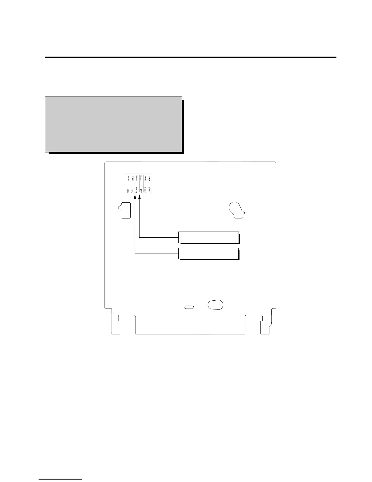
2-2-1 The number and position of test point
Test point : TP601 (Control Pulse)
TP602 (H’D S/W -Trigger)
TP301 (Envelope)
TP302 (Audio output)
TP303 (Video output)
Fig. 2-3 Location of Test point (Main PCB-Top View)
2-2-2 ACE Head Position (X-Point) Adjustment
(See the 2-2-1(d) ACE Head Position (X-Point) Adjustment
on page 2-2 of the Mechanical Manual)
1) Playback the alignment tape (Color bar).
2) Intermittently short-circuit the two test points on
Main PCB to set the adjustment mode.
(See Fig. 2-2)
3) Press the “5” button of remote control then adjust-
ment is operated automatically. (See Fig. 2-1)
4) Connect the CH-1 probe to TP301 (Envelope) the
CH-2 probe to TP602 (H’D switching pulse) and
then trigger to CH-1.
5) Insert the (-) driver into the X-Point adjustment
hole and adjust it so that envelope waveform is
maximum.
6) Turn the Power off.