EasyManua.ls Logo

Samsung WF45H6300 User Manual

Samsung WF45H6300
10 pages
To Next Page IconTo Next Page
Page #1 background imageLoading...
Page #1 background image
Fast Track Troubleshooting
Model: WF45H6300
Publication #DrMy WF45 Production Date 9/2/14
IMPORTANT SAFETY NOTICE “For Technicians Only This service data sheet is
intended for use by persons having electrical, electronic, and mechanical experience and knowledge
at a level generally considered acceptable in the appliance repair trade. Any attempt to repair a
major appliance may result in personal injury and property damage. The manufacturer or seller
cannot be responsible, nor assume any liability for injury or damage of any kind arising from the use
of this data sheet.
Bulletins:
Support Information:
HELP: 1-888-751-4086 (Tech Sup. ASC/SSD) - 1-866-894-0637 (Tech Sup. - FE/ME)
GSPN: http://gspn3.samsungcsportal.com/main.jsp
PLUS ONE: http://my.plus1solutions.net/clientPortals/samsung
**With the Power On**
**Test Mode** With the Power Off
SERVICE MODE: WITH POWER ON - PRESS: Soil Level + Delay End
TEST FUNCTION PRESS Enter and Exit
1 Cycle Count Temp
2 Version Soil Level
3
Board Input Test (Move Jog
dial to check LED) (See Chart
at bottom)
Delay End
4
DIAGNOSTIC ERROR CODE
CHECK (See Below)
SPIN - Turn dial either clockwise (c.w) or
counter c.w.
5
SPIN TEST ( RPM) (ref:
NB***)
Delay End + Temp for 3sec. (To Pause: press
- START/PAUSE)
QUICK TEST MODE:WITH POWER OFF - PRESS: Spin + Soil Level + POWER
NB*** Spin Test will NOT test Hall Sensor in this mode. NOTE: ALWAYS
remember to offset counter weight when spin testing an empty machine
FACT: It is NORMAL for this unit to be unbalanced until 350-400 RPM
counter weights will only align correctly after this RPM is reached
Activate the SERVICE MODE first (ref: above).
Press the SPIN key to start DIAGNOSTIC CODE check mode. .
To cycle through the diagnostic codes (d1, d2, d3, etc.), turn the rotary cycle selector
(knob) either clockwise or counter clockwise.
When turning the rotary selector key (knob) in one direction, it shows diagnostic codes
from the latest (d1).
Now when turning the knob in the opposite direction it shows the diagnostic codes in the
reverse order. E.g. When it stops at “d5” and then turn backwards, it shows from “d4” to
“d”. (Refer to Diag. Code interpretation).
Service mode Option 4:
DIAGNOSTIC ERROR CODE CHECK
Use the Board input test under service mode to test water temp,
during normal wash operation.
Service mode Option 3:
Board Input Test Chart
TEST FUNCTION PRESS Enter and Exit
1 Water Valve Test
TEMP
**Door Lock Must be Activated 1
st
before running Component **
2 Door Lock SPIN
3 Heater SUPER SPEED
4 Drain Pump /Bubble Pump SOIL
5 EEPROM MEMORY CLEAR DELAY END + POWER (with POWER OFF)
LED 1st LED is on 2nd LED is on
3rd LED on 4th LED On 5th LED on
Display
Water Temp
C
Water Temp
F
Door Status
OP=Open
CL=Closed
Door lock
sw Status
UL=
unlocked
LO=Locked
Water
Frequency
Question and Answer IconNeed help?

Do you have a question about the Samsung WF45H6300 and is the answer not in the manual?

Samsung WF45H6300 Specifications

General IconGeneral
TypeFront Load
Capacity4.5 cu. ft.
Energy Star CertifiedYes
Max Spin Speed1300 RPM
Number of Cycles12
Steam CleaningYes
Smart ControlNo
ColorWhite
Voltage120V
Wash CyclesNormal, Heavy Duty, Permanent Press, Delicates, Rinse + Spin, Spin Only, Active Wear, Bedding

Summary

Quick Test Mode and Service Mode Operation

Quick Test Mode Operation

Accesses diagnostic functions by pressing buttons before turning on the unit.

Service Mode Operation

Enables diagnostic tests and error code checks by pressing specific button combinations with the unit powered on.

Diagnostic Error Code Retrieval

Procedure to retrieve and cycle through stored error codes via the service mode interface.

Board Input Test Procedure

Details how to test various board inputs like water temp, door status, and water frequency.

Component Testing Procedures

Door Lock Switch Resistance Test

Measures the resistance of the door lock switch for proper function and continuity.

Water Level Sensor Diagnostic

Verifies water level sensor frequency and pin resistances to detect faults.

Water Valve Electrical Checks

Checks water supply valve resistance and voltage to ensure proper operation.

Motor Resistance Diagnostics

Measures the resistance of the drain and drum motors for operational integrity.

Error Code Troubleshooting Guide

Sensor, Motor, and Supply Errors (LE1, 3E, nF)

Details corrective actions for LE1, 3E/E3/bE, and nF errors related to sensors and water supply.

Drain and Communication Errors (nd, AE)

Provides troubleshooting steps for nd (drain) and AE (communication) errors.

Door and Heater Errors (dL, Hr)

Explains how to resolve dL/LO (door) and Hr (heater) errors, including switch and sensor checks.

Further Error Code Troubleshooting

Leakage and Overflow Errors (LE, OE)

Addresses LE (water leakage) and OE (overflow) errors, focusing on hose and drainage checks.

Sensor and Unbalance Errors (tE, dc)

Covers tE (temperature sensor) and dc (unbalance) errors, including sensor connections and load balance.

Additional Error Code Explanations

Foaming and PBA Errors (SUdS, 8E)

Explains SUdS/Sd (foaming) and 8E1/8E2/8E (Mems PBA) error codes and their resolutions.

System and Controller Errors (SF1, SF3)

Details SF1/SF2/SF3 errors related to microcontroller operation and PBA replacement.

Troubleshooting Common Operational Issues

Door Lock/Unlock Failures

Addresses issues where the door fails to lock or unlock properly, checking alignment and PCB.

Spin Issues and Wet Load Problems

Covers problems with the washer not spinning or the load remaining too wet, checking balance and spin speed.

Start and Cycle Interruption Issues

Troubleshoots issues with the washer not starting or stopping unexpectedly during a cycle.

Water Filling and Draining Problems

Guides on resolving situations where the washer won't drain or fails to fill with water.

Main and Inverter PCB Identification

Main PCB Connector Overview

Identifies connectors (CN6, CN9, CN1, CN10) on the main control board for signal tracing.

Inverter PCB Connector Overview

Maps connectors (CN2, CN1, CN6, CN4, CN7, CN5) on the inverter board for motor control signals.

Wiring Diagrams and PCB Connections

Main/Inverter PCB Wiring Schematics

Details the schematic connections between the main control, inverter boards, and motor.

Sub PCB and Power Wiring

Illustrates the wiring for the sub-PCB and the main power cord connections.

Inverter Board Diagnostic Testing

Motor/Sensor Connector Resistance Tests

Step-by-step guide for measuring resistance at motor and Hall sensor connectors on the inverter board.

Inverter Communication Connector Test

Procedure for testing the communication connector on the inverter board.

Key Product Features

Capacity and Display Features

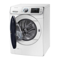
Highlights the large capacity, 8" LCD Touch Screen, and user interface capabilities.

Smart Control and Care Features

Explains Smart Control for remote operation and Smart Care for automatic error monitoring.

Performance and Drum Technologies

Details PowerFoam, SpeedSpray, VRTplus, Deep Steam, Pure Cycle, Diamond Drum, and DD Motor features.

Related product manuals