S&C Instruction Sheet 716-504 13
Installation
CAUTION
The operator directly drives the interrupters
open and closed through a simple high-
speed power train leading from the top of
the operator, through a horizontal interphase
linkage enclosed in a steel-sheathed high-
speed base, to reciprocating-action insulated
operating rods that pass through the center of
the insulating support columns. Permanently
lubricated bearings are used throughout the
power train. The high-speed base has been
fully pre-assembled and adjusted at the
factory. DO NOT disassemble the high-
speed base or high-speed power train.
Damage to the high-speed base and personal
injury may result.
Step 4
Loosely bolt the high-speed base to the
support arms using the ½–12×2-inch hex-head
galvanized steel cap screws, at washers, and
self-locking hex nuts furnished.
Lubricate the bolts to facilitate tightening.
Use a level to verify the high-speed base is hori-
zontal, both lengthwise and sideways. Adjust
the lower set of anchor bolt nuts at the pedestals
to achieve level. See Figure3 on page11.
If necessary, loosen the ⅝–11×1¼-inch hex
head galvanized steel cap screws that attach
the support arms to the mounting pedestals,
reposition the support arms, and retighten the
cap screws.
Step 5
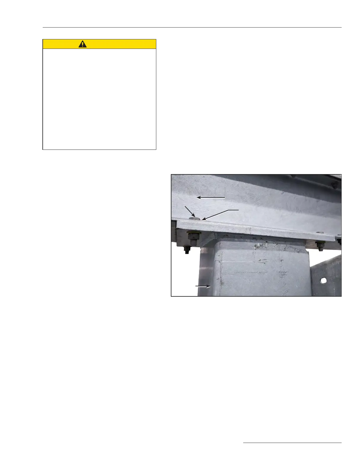
Examine the bottom of the high-speed base
where it comes in contact with the support
arms. If necessary, install shims between
the high-speed base and the support arms to
compensate for any gaps greater than ⅛-inch
(3.175 mm) between the mating surfaces. See
Figure6.
Tighten the bolts on the high-speed base to
75 ft./lbs.
On 69-kV circuit-switchers with 48-inch
phase spacing: support arm gussets are not
used; the high-speed base is attached atop the
mounting pedestal using ⅝–11×2¼-inch hex-
head galvanized steel cap screws, flat washers,
and self-locking hex nuts. Shim between the
high-speed base and the pedestal if necessary.
Step 6
Refer to the catalog drawing and attach the
support brace to the support arms, using the
spacers, ½–12×2-inch hex-head galvanized
steel cap screws, at washers, and self-locking
hex nuts furnished. Securely tighten the
associated cap screws.
Figure 6. Shim under the high-speed base for gaps of more than ⅛-inch.
(69 kV shown, 115 and 138 kV similar.)
Pedestal
High-speed base
Shims
(if required)
Bolts