32 S&C Instruction Sheet 716-504
Installation
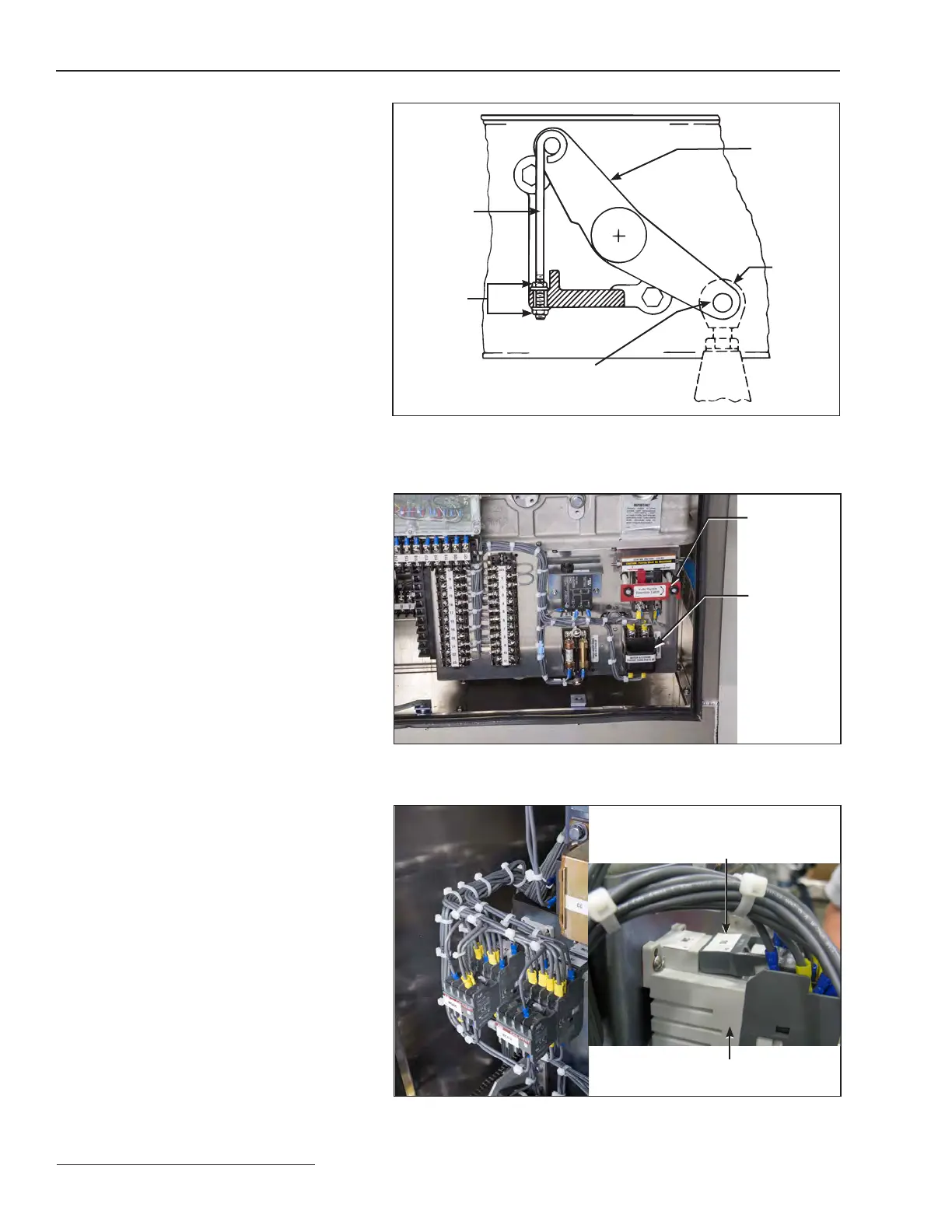
Figure 36. Check that the interphase drive lever has been connected to
the uni-ball coupling and check that the adjustable locking rod has been
removed.
Interphase
drive lever
Adjustable
locking rod
(marked
with a black/
yellow striped
label)
¾-inch
stainless-steel pin
and cotter pin
Uni-ball
coupling
¼-inch–20
locknut
Step 32
Replace the access cover on the side of
each transition box and securely tighten the
associated 5⁄16–18×¾-inch hex-head stainless
steel cap screws.
Step 33
Replace the bottom plates to the underside of
the high-speed base and securely tighten the
associated ½–13×1¼-inch galvanized steel cap
screws, at washers, and nuts. See Figure7 on
page14.
Step 34
Insert the motor-and-closing circuit fuse
holders. Then close the control power knife
switch. See Figure37.
Step 35
The disconnect blades should be in the Open
position attained in Step 26 on page25.
Press the CLOSE pushbutton or send a close
signal to the switch operator. See Figure30 on
page 26. (Trip and close pushbuttons are not
included on operators specified with Catalog
Number Suffix “-J.” In such instances, momen-
tarily jumper terminals 1 and 3 to close the
circuit-switcher.)
The motor-driven cam in the stored-energy
mechanism will immediately start retracting.
Simultaneously, the take-off shaft at the rear
of the operator housing will turn to drive the
interphase pipe assembly, closing the discon-
nect. When the disconnect has completely
closed, the closing latch will release, discharg-
ing the closing springs. This action closes the
interrupters. The switch-position indicator on
the high-speed base will move to the Closed
position. See Figure 41 on page 34. Further, if
the position-indicating lamp option has been
specified, the red lamp will light. See Figure 30
on page 26.
Figure 37. The motor and closing circuit fuse holders and the control
source knife switch.
Figure 38. Check the open and close motor contactors, auxiliary contact
blocks, and surge suppressors behind the operator side panel.
Knife switch
Motor and
closing circuit
fuse holder
Surge suppressor out of place.
Push the surge support
(if present) back into place.
Motor contactors and auxiliary
contactors should be fully seated
 Loading...


