12 S&C Instruction Sheet 716-504
Installation
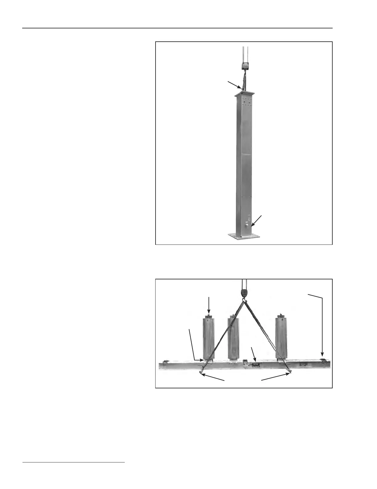
Figure 4. Lift the pedestal into position.
Figure 5. Hoist the high-speed base using a crane.
Lifting angle
Interrupter
shipping bracket
and clamps
Interrupter lifting bracket
Protective cover at pole-unit
mounting position.
See Step 12.
(b) Install the temporary eyebolts into the
holes provided at the top of the mounting
pedestal. Attach the lifting slings to the
eyebolts. See Figure4.
(c) Lift the pedestal over the anchor bolts.
Before lowering, make sure the ground-
ing pad is positioned properly for the
installation. Refer to the accompanying
catalog drawing for details. See Figure4.
(d) Lower the pedestal onto the anchor bolt
nuts and at washers. Loosely secure a
at washer and nut to each anchor bolt.
See Figure 3 on page 11. Remove the
lifting slings and eyebolts.
(e) Adjust the lower set of anchor-bolt nuts
to plumb and level the pedestal. The
upper set of anchor bolt nuts should
remain loosely attached. See Figure 3 on
page 11.
(f) Attach the support arms to the mounting
pedestals as shown on the catalog
drawing using ⅝–11×1¼-inch hex-head
galvanized steel cap screws and at
washers furnished. Torque the cap
screws to 75ft-lbs. Also see Figure1 on
page 10.
(g) Install the covers to the tops of each
mounting pedestal using ½–13×2-inch
hex-head galvanized steel cap screws,
at washers, and self-locking hex nuts
furnished. (Not applicable to 69-kV
circuit-switchers with 48-inch phase
spacing.) Securely tighten the cap
screws.
Step 3
Attach the supplied lifting angles to the high-
speed base using the ½–12×1¼-inch hex-head
galvanized steel cap screws furnished. See
Figure5. Securely tighten the cap screws, then
attach four suitable lifting slings to the lifting
angles. Unbolt the high-speed base from the
shipping skids and lift the high-speed base—
with interrupters attached—atop the support
arm gussets, as shown on the catalog drawing.
Avoid sudden starts and stops. Verify that the
switch-position indicator on the base is visible
on the desired side (this is also the side on which
the operator door will open.)
On the 69-kV circuit-switchers with
48-inch phase spacing: support arm gussets
are not used; the high-speed base is attached
atop the mounting pedestal using ⅝–11×2¼-
inch hex-head galvanized steel cap screws, flat
washers, and self-locking nuts.
Eye bolts
Grounding pad
Position
indicator