S&C Instruction Sheet 716-504 21
Installation
Connecting the Operator and
Pole-Units to the
High-Speed Power Train
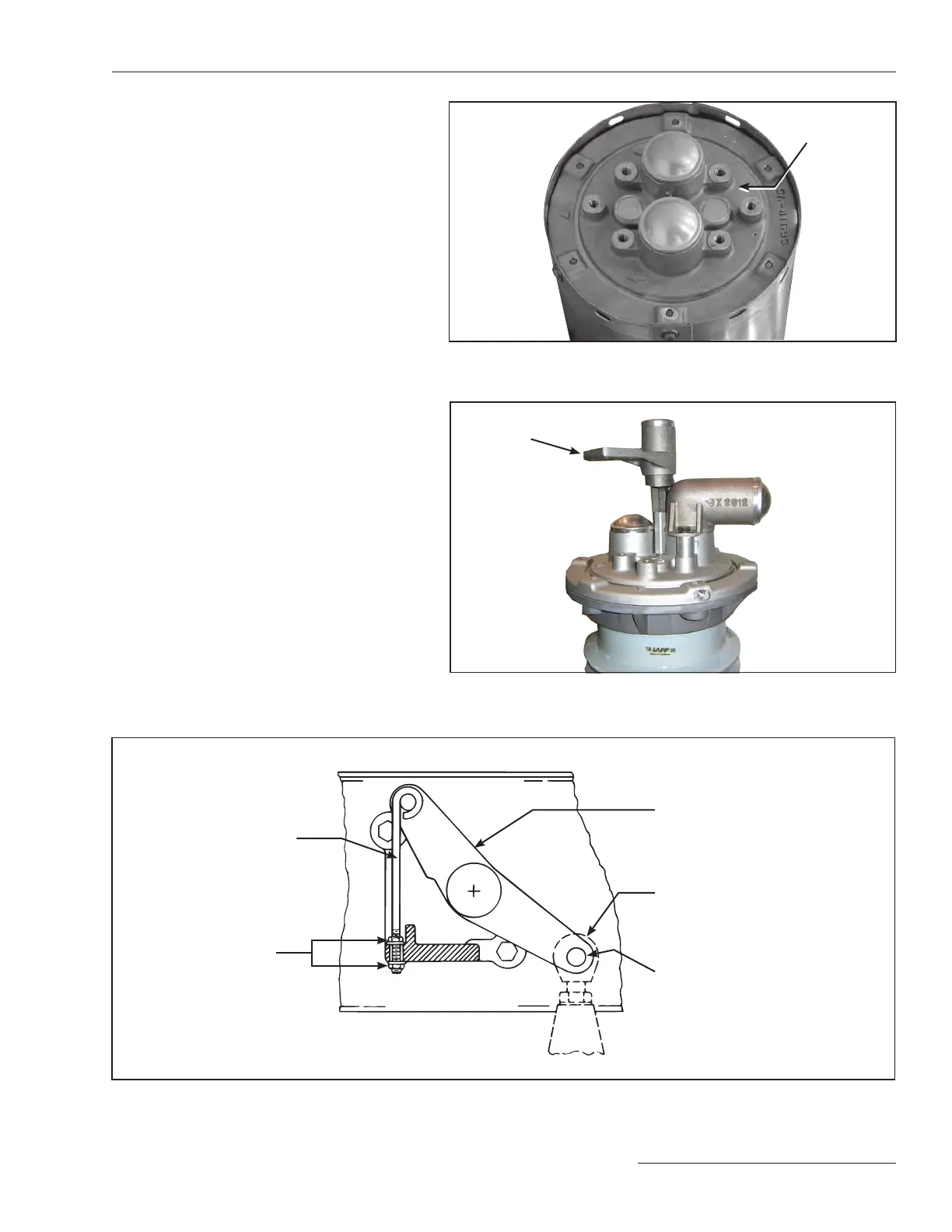
Step 18
Attach the uni-ball coupling on the operator
connecting link to the interphase drive lever in
the high-speed base using the ¾-inch stainless
steel pin and cotter pin retained from Step8.
See Figure 21. An adjustable locking rod
(marked with a black/yellow striped label) is
furnished factory-connected to the interphase
drive lever; turn the associated ¼–20 locknuts
as required to raise or lower the interphase
drive lever and thus facilitate insertion of the
stainless steel pin.
Step 19
Remove the lower ¼–20 locknut that retains
the adjustable locking rod, then remove and
discard the adjustable locking rod and locknuts.
See Figure21.
Figure 19. Wire brush the surface of the end casting and preparing with
aluminum-connector compound.
Figure 20. Attach the terminal pad. Shown with Option “-N” Enhanced-
Visibility low-pressure indicator.
Figure 21. Attach the Uni-ball coupling to the interphase drive lever.
Interphase drive lever
Adjustable locking rod
(marked with a black/
yellow striped label)
¾-inch
stainless steel pin
and cotter pin
Uni-ball coupling
End casting
¼-inch–20 locknut
Terminal pad