22 S&C Instruction Sheet 716-504
Installation
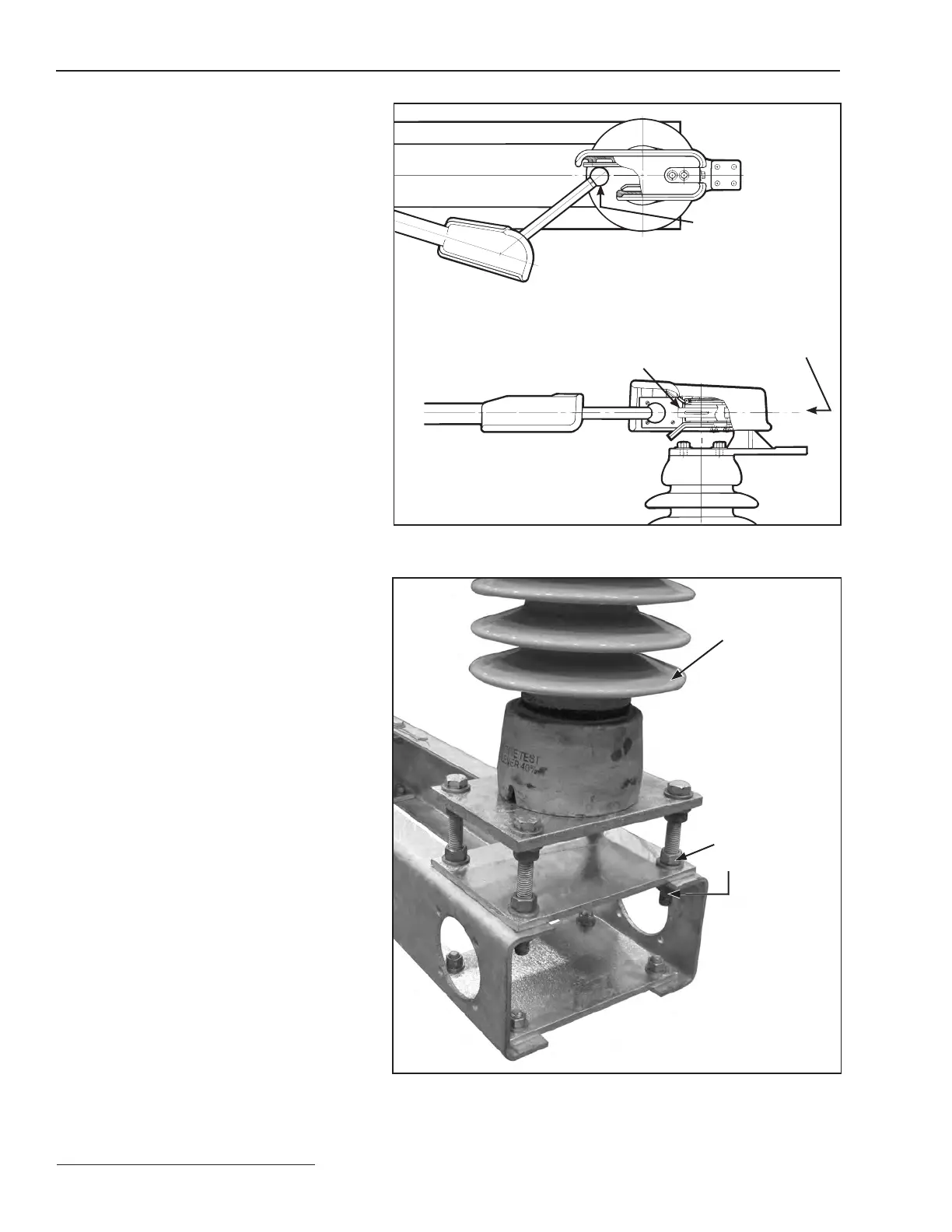
Step 20
Open the disconnect blade on each pole-unit.
When the disconnect-blade corona-ball contact
is clear of its jaw contact ngers as indicated
in Figure22 (top view), check that the blade
centerline has not shifted up or down by more
than ¼-inch—as measured to the centerline of
the jaw contact. See Figure22 (side view). If
the blade centerline has shifted by more than
¼-inch, loosen the leveling locknuts located
under the associated jaw-contact support
insulator. See Figure23. Adjust the locknuts as
necessary to shift the jaw-contact centerline
to correspond to that of the blade centerline,
within ¼-inch, then tighten the locknuts.
Figure 22. Check the alignment of the disconnect blade and jaw contact.
Figure 23. Adjust the leveling-screw locknuts.
Top View
Side View
Disconnect-blade
corona-ball contact
Jaw-contact finger
Center-line of disconnect
blade and jaw-contact
assembly
Jaw-contact
support insulator
Leveling
locknuts