24 S&C Instruction Sheet 716-504
Installation
Step 22
Attach the clevis end of the interphase drive
link to the longer arm of the bell-crank on the
high-speed base using a ½-inch stainless steel
pin and cotter pin furnished. See Figure26.
Step 23
Connect the interphase drive to the switch
operator as follows:
(a) Attach the “C”-shaped clevis at the
lower end of the vertical-operating-pipe
assembly to the take-off shaft on the
rear of the operator using a ⅝-inch
stainless steel pin and stainless steel
“X” washer furnished. See Figure25.
(b) Attach the straight clevis at the upper
end of the vertical-operating-pipe
assembly to the shorter of the bell-crank
arms on the high-speed base using the
⅝-inch stainless steel pin and cotter pin
furnished. See Figure26. If necessary,
loosen the locknuts at the top and
bottom of the vertical operating pipe
and rotate the pipe so the connection
can be made.
(c) Tighten the locknuts.
Figure 26. Connect the interphase pipe assembly and vertical-operating pipe assembly. Attachment of the interphase drive link to
interphase pipe is different on circuit-switchers rated 69 kV (with 48-inch phase spacing). Refer to the catalog drawing for details.
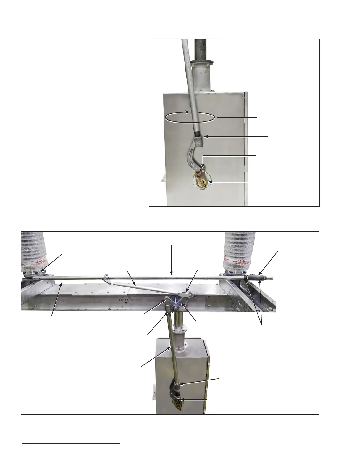
Figure 25. Rear of switch operator.
Locknut
Take-off shaft
⅝-inch
stainless steel
pin and “X” washer
Operator Detail
View
Rotate clockwise to
increase blade travel
½-inch stainless steel pin,
galvanized steel spacers,
and stainless steel
“X” washers
⅝-inch
stainless steel
pin and cotter pin
Locknut
Interphase drive link
Interphase pipe assembly
Adjustable coupling
Bell crank
Clevis
Locknut
Insulating support
column drive lever
Vertical-operating-pipe assembly
⅝-inch
stainless steel pin and “X” washer
Locknut