10 S&C Instruction Sheet 719-501
Operation
The following operating instructions assume the
switch-operator output shaft has been connected to the
circuit-switcher power train, the electrical connections to
the control source have been completed, and the switch
operator has been correctly adjusted in accordance with
S&C Instruction Sheet 719-500, “S&C Type CS-1A Switch
Operators: Installation.” Figure 1 on page 7 illustrates a
Type CS-1A Switch Operator connected to an integer-style
Mark V Circuit-Switcher.
Do not assume the switch-operator position necessarily
indicates the Open or Closed position of the circuit-
switcher. Upon completion of an Opening or Closing
operation (electrical or manual), make sure the following
conditions exist:
•
The switch-operator position indicator displays “Open”
or “Closed” to indicate the switch operator has moved
through a complete operation. See Figure 1 on page 7.
Also, if furnished, note the position-indicating lamps.
See Figure 2 on page 8.
• The circuit-switcher position indicator, located on the
switch-operator output shaft, is in agreement with the
switch-operator position indicator. See Figure 1. Both
indicators should show “Open” or “Closed.”
•
The circuit-switcher disconnect blade on each pole-unit
is fully open or fully closed.
Then, tag and padlock the switch operator in accor-
dance with standard system operating procedures. In all
cases, make sure the switch operator is padlocked before
“walking away.”
Correct operation of the circuit-switcher depends on
charging and latching the stored-energy source within
each brain as the disconnect blades move to the fully Open
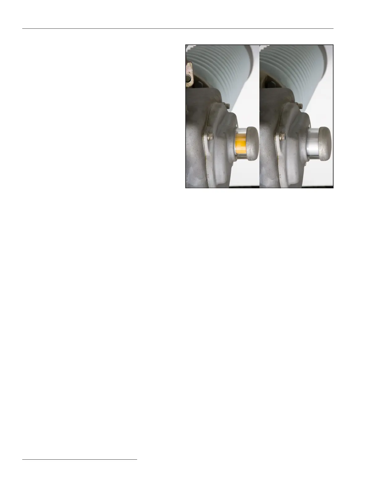
position and the interrupters close. The interrupter target
located on the side of each brain housing appears yellow
when the interrupter is open. The target appears gray
(normal) when the interrupter is closed.
Because the interrupters are closed as the circuit-
switcher blades move to the fully Open position, the target
appears yellow only briefly during the Opening operation.
The target should never appear yellow when the circuit-
switcher is in the fully Open or fully Closed position. See
Figure 1 on page 7 and Figure 3.
Figure 3� The interrupter target�
Yellow
(open)
Gray
(closed)
 Loading...


