I
INSTALLATION
I
Do not remove the interrupter containers until the
installation has been completed.
Step 1
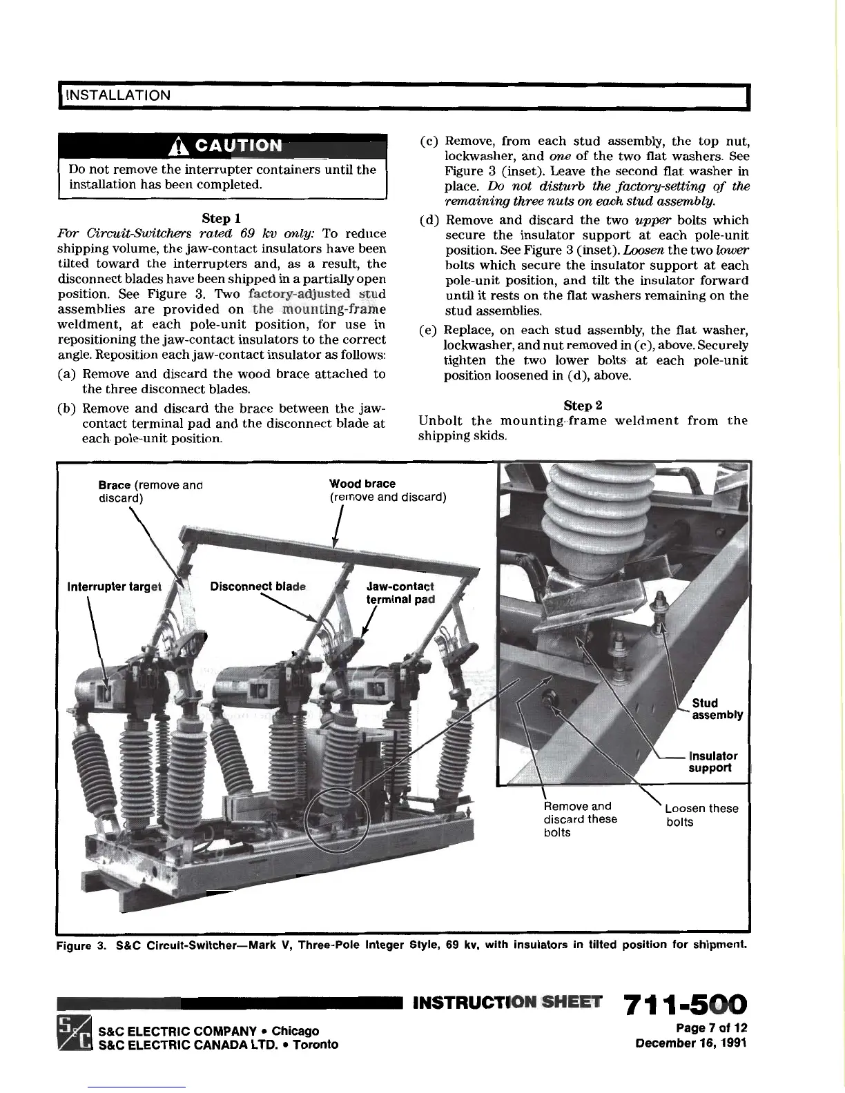
For Circuit-Switchers rated 69 kv only: To reduce
shipping volume, the jaw-contact insulators have been
tilted toward the interrupters and, as a result, the
disconnect blades have been shipped in a partially open
position. See Figure 3. Two factory-adjusted stud
assemblies are provided on the mounting-frame
weldment, at each pole-unit position, for use in
repositioning the jaw-contact insulators to the correct
angle. Reposition each jaw-contact insulator as follows:
(a) Remove and discard the wood brace attached to
the three disconnect blades.
(b) Remove and discard the brace between the
jaw-
contact terminal pad and the disconnect blade at
(c) Remove, from each stud assembly, the top nut,
lockwasher, and one of the two flat washers. See
Figure 3 (inset). Leave the second flat washer in
place.
Do
not disturb the factory-setting of the
remaining three nuts on each stud assembly.
(d) Remove and discard the two upper bolts which
secure the insulator support at each pole-unit
position. See Figure 3 (inset). Loosen the two lower
bolts which secure the insulator support at each
pole-unit position, and tilt the insulator forward
until it rests on the flat washers remaining on the
stud assemblies.
(e) Replace, on each stud assembly, the flat washer,
lockwasher, and nut removed in (c), above. Securely
tighten the two lower bolts at each pole-unit
position loosened in (d), above.
Step 2
Unbolt the mounting-frame weldment from the
each. pole-unit position.
shipping skids.
Brace
(remove and
discard)
Wood brace
(remove and discard)
Interrupter target
Disconnect blade
’
Stud
P’
assembly
discard these
bolts
bolts
Figure 3. S&C Circuit-Switcher-Mark V, Three-Pole Integer Style, 69 kv, with insulators in tilted position for shipment.
q
S&C ELECTRIC COMPANY
l
Chicago
S&C ELECTRIC CANADA LTD.
l
Toronto
INSTRUCTIO1S
SHEE7
7
11.500
Page 7 of 12
December
16,199l