S&C Instruction Sheet 662-510 17
Switching with Uni-Rupter
®
Interrupters
WARNING
Dual-purpose front barriers must be wiped clean
before placing them in the “Slide-in” position. In
addition, do not leave dual-purpose front barriers
in the “Slide-in” position for more than one week.
These barriers are intended for temporary use only
to iso late the fuse from the main contacts of the
Uni-Rupter Interrupter while work is being performed.
If the barri ers are left in the “Slide-in” position for
extended periods of time, there is the possibility
of corona discharge to the barriers. Prolonged
exposure to corona discharge may damage the
barriers and result in a flashover and injury.
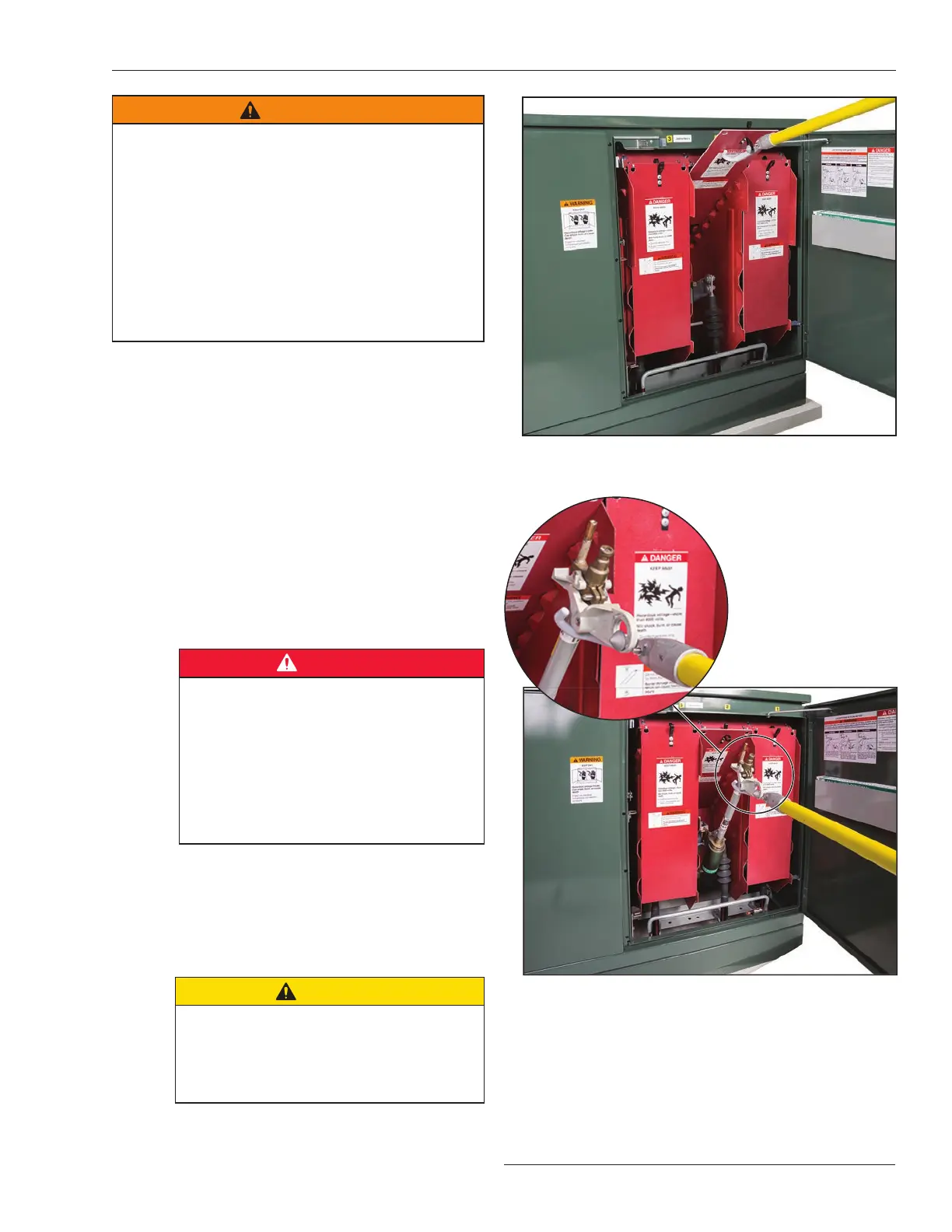
STEP 3. For all fuses except 25-kV Fault Fiter
Electronic Power Fuses: Install a fuse into its
hinge as follows:
(a) Position the Grappler tool’s cone in the fuse
pull-ring and cradle the fuse in the Grappler
tool’s prongs. See inset of Figure19.
(b) Grasp the universal pole with both hands
(approxi mately 2 feet (610 mm) apart), with
one hand at the opposite end of the pole from
the Grappler tool.
(c) Lift the fuse and lower it into its hinge. See
Figure 19. Make sure the fuse is securely
seated in the hinge and then disengage the
Grappler tool from the fuse. See Figure 20 on
page 18.
DANGER
Make sure the fuse is kept away from the
con tacts of the Uni-Rupter Interrupter
during installation of the fuse into its hinge to
prevent reestablishment of the circuit. It is
recommended that the associated dual-
purpose front barrier be placed in the
“Slide-in” position whenever a fuse is
open or is being installed into or removed
from its hinge.
STEP 4. For 25-kV Fault Fiter Electronic Power
Fuses: De-energize, test, and properly ground
the mounting in accordance with local operating
practices, and then install the fuse in its
mounting by hand using suitable personal
protective equipment (PPE).
CAUTION
Do not close a compartment door when
any of the associated fuses are in the Open
position. If the door is closed, it will strike
the fuse pull-ring. The door may be closed
if the fuse is removed from its mounting.
Figure 18. Inserting the dual-purpose front barrier into the
“Slide-in” position using a Grappler tool.
Figure 19. Installing a fuse using a Grappler Handling Tool. The
inset image shows a close-up of a Grappler tool in position to
install the fuse.
 Loading...
