S&C Instruction Sheet 662-510 21
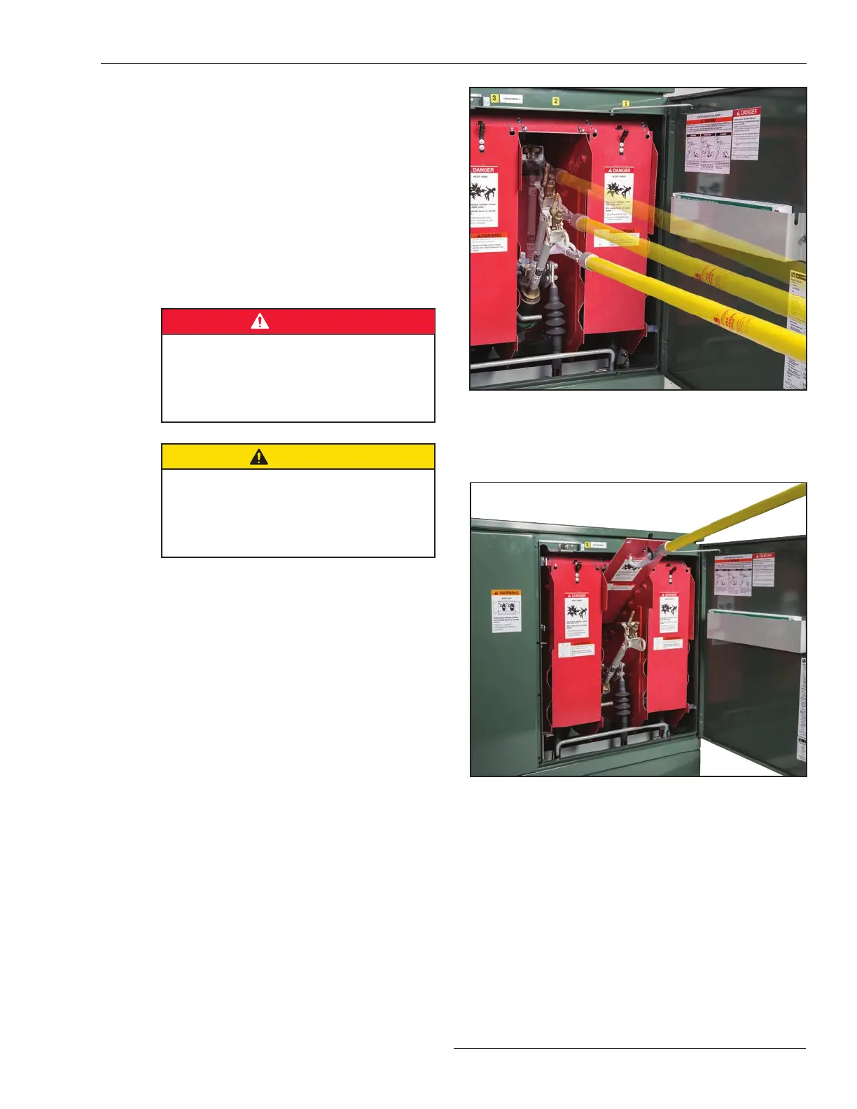
Figure 24. Opening the fuse.
Figure 25. Inserting dual-purpose front barrier into the “slide-
in” position using a Grappler tool.
Switching with Uni-Rupter
®
Interrupters
STEP 4. Pull the fuse vigorously through its full travel
without hesitation at any point. See Figure 24. A
downward force should be maintained on the
universal pole through the fuse-opening
operation to counteract any tendency the fuse
may have to bounce toward the Closed position.
Note: The Uni-Rupter Interrupter is designed to
require a hard pull to unlatch the fuse, thus
reducing the possibility of an incomplete
opening operation.
STEP 5. Remove the Grappler tool from the fuse pull-
ring.
DANGER
Although a fuse in the fully Open position
provides visual evidence of an open
circuit, it does not nec essarily mean the
Uni-Rupter Interrupter, the load-side
hinge, or the fuse is de-energized.
CAUTION
Do not close a compartment door when
any of the associated fuses are in the Open
position. If the door is closed, it will strike
the fuse pull-ring. The door may be closed
if the fuse is removed from its mounting.
STEP 6. S&C recommends the dual-purpose front
barrier associated with the fuse to be removed
be inserted into the “Slide-in” position. Use
the Grappler tool for this, as illustrated in Figure
25. Note that the barrier is sup ported on the
Grappler tool’s prongs and held there by
engagement of the lifting ring with the Grappler
tool’s cone.
STEP 7. For all fuses except 25-kV Fault Fiter
Electronic Power Fuses: Remove the fuse
from its hinge as fol lows:
(a) Grasp the universal pole with both hands
(approxi mately 2 feet (610 mm) apart), with
one hand at the opposite end of the pole from
the Grappler tool.
(b) Position the Grappler tool’s cone in the fuse
pull-ring and cradle the fuse in the Grappler
tool’s prongs. See Figure26 on page22.
(c) Stand in a normal, upright position facing
the uni versal pole. Move the pole forward
until resistance between the Grappler
tool and the fuse is felt, or approximately
2 inches (51 mm).
(d) Then, remove the fuse from its hinge with a
forward and upward lifting motion. See
Figure 27 on page 22.
 Loading...
