Do you have a question about the Sansui 300 and is the answer not in the manual?
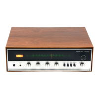
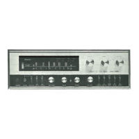
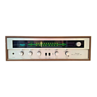
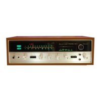
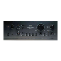
Illuminated FM/AM tuning scales and the FM stereo reception indicator.
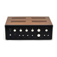
Tuning knob, tuning meter, power switch, and headphone jack for device operation.
Bass, Treble, Volume, and Balance controls for adjusting audio output.
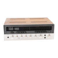
Tuning knob for station selection and selector switch for input sources.
Mode, Loudness, MPX Noise Canceler, and Tape Monitor switches for audio features.
Guide for connecting speakers, matching polarity, and impedance considerations.
Instructions for connecting turntables to PHONO or AUX inputs.
Steps for setting selector, mode, and balancing sound levels for record playback.
Tips for optimal playback of monophonic records on a stereo system.
Details on using the built-in ferrite bar and external AM antennas.
Methods for connecting indoor dipole, 300-ohm, and 75-ohm FM antennas.
Steps for tuning and receiving FM broadcasts using the receiver.
Instructions for setting the selector and tuning AM broadcasts.
Illustrations for connecting FM and AM antennas for optimal reception.
Connecting tape recorders via DIN or pin plug cables.
Instructions for monitoring recorded tapes during the recording process.
Setting selector, mode, and starting tape recording.
Setting tape monitor switch and starting playback of recorded tapes.
Diagrams illustrating tape recorder connections for recording and playback.
Tips for minimizing AM noise from location or electrical interference.
Methods for minimizing FM noise from weak signals or appliances.
Troubleshooting general noise from electrical appliances or interference.
Recommendations for maintaining optimal heat dissipation for the amplifier.
Guidance on connecting phonographs and tape recorders using shielded cables.
Resolving booming or howling noise during record or tape playback.
Instructions for grounding the receiver to reduce noise and improve stability.
Information on the use and capacity of the rear panel AC outlet.
Steps for setting the receiver voltage selector for different regions.
Procedure for identifying and replacing a blown main power fuse.
Diagnosing and replacing quick-acting fuses in the amplifier channels.
Advice on matching speaker power ratings to the amplifier's output capacity.
Instructions for disassembling the front panel, bonnet, and bottom plate.
Illustration of the dial mechanism components and their arrangement.
Procedure for aligning the FM intermediate frequency transformer circuit.
Procedure for aligning the FM discriminator circuit for optimal signal.
Procedure for aligning the FM local oscillator and associated tuning coils.
Procedure for aligning the FM high-frequency amplifier circuits.
Procedure for tuning the 67kHz trap in the FM multiplex section.
Procedure for aligning the 19kHz tuning coil for FM multiplex reception.
Procedure for aligning the 38kHz tuning coil for FM multiplex reception.
Adjusting the separation VR for optimal stereo separation in FM multiplex.
Procedure for aligning the AM intermediate frequency transformers.
Procedure for aligning the AM local oscillator and tuning trimmer.
Procedure for aligning the AM high-frequency amplifier circuits.
List of components and their locations for the Power Block F-1152A.
List of components and their locations for the Tone Control Block F-1156.
List of components and their locations for the Equalizer Amplifier Block F-1157.
List of components and their locations for the FM IF Block F-1165B.
List of components and their locations for the Driver Amplifier Block F-1119B.
List of components and their locations for the AM Tuner Block F-1172A.
List of components and their locations for the Multiplex Block F-10991.
List of components and their locations for the FM Stereo Indicator Block F-1203A.
List of miscellaneous components and their physical locations on the chassis.
| Damping Factor | 20 |
|---|---|
| Frequency Response | 20Hz to 20kHz |
| Channel Separation | 50dB (line) |
| Speaker Load Impedance | 8Ω to 16Ω |
| Input Impedance | 50kΩ |
| Speaker Impedance | 4-16Ω |
| Input Sensitivity | 2.5mV |