Do you have a question about the Sansui 7000 and is the answer not in the manual?
Steps for disassembling the unit's exterior components.
Explains the dial mechanism assembly.
Identifies key test points for alignment procedures.
Step-by-step guide for FM circuit calibration.
Alignment steps for the FM multiplex section.
Step-by-step guide for AM circuit calibration.
Details on the AM Intermediate Frequency characteristics.
List and layout for FM IF circuit components.
List and layout for FM MPX circuit components.
Component placement diagram for F-1322 board.
Component placement diagram for F-1316 board.
List and layout for Power and Protector circuit components.
Component placement diagram for F-1317 board.
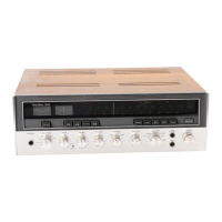
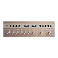
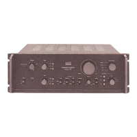
Visual guide showing component locations on the chassis.
| Power Output | 70 watts per channel into 8Ω (stereo) |
|---|---|
| Frequency Response | 10Hz to 30kHz |
| Total Harmonic Distortion | 0.5% |
| Speaker Load Impedance | 4Ω to 16Ω |
| Channel Separation | 50dB (MM) |
| Output | Headphones |
| Input Sensitivity | 2.5mV (MM), 200mV (line) |
| Type | Solid State |