Do you have a question about the Sansui A-7 and is the answer not in the manual?
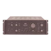
Detailed technical specifications for the Sansui A-9 integrated amplifier, including power output and frequency response.
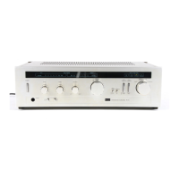
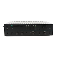
Detailed technical specifications for the Sansui A-7 integrated amplifier, including power output and frequency response.
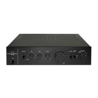
Detailed technical specifications for the Sansui A-5 integrated amplifier, including power output and frequency response.
Functional block diagram illustrating the internal circuitry and signal flow of the Sansui A-9 amplifier.
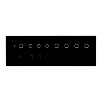
Functional block diagram illustrating the internal circuitry and signal flow of the Sansui A-7 amplifier.
Functional block diagram illustrating the internal circuitry and signal flow of the Sansui A-5 amplifier.
Location and part numbers for components on the F-3336 Power Amplifier circuit board.
Location and part numbers for components on Mic, EQ, and Control Volume circuit boards.
Location and part numbers for components on Tone, Main Amp, and Power Supply circuit boards.
Identification of external controls, indicators, and internal components for the Sansui A-9 model.
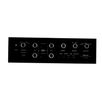
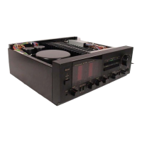
Identification of external controls, indicators, and internal components for the Sansui A-7 model.
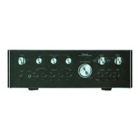
Identification of external controls, indicators, and internal components for the Sansui A-5 model.
Comprehensive schematic diagrams detailing the complete circuitry of the Sansui A-9/A-7/A-5 amplifiers.
Step-by-step guide for setting the driver circuit bias current on A-9/A-7 models.
List of packaging materials included with the amplifier for safe transport and delivery.
List of accessories, such as operating instructions and manuals, supplied with the unit.
| Input Sensitivity | 2.5mV (MM), 150mV (line) |
|---|---|
| Frequency Response | 10Hz to 50kHz |
| Input Impedance | 50k ohms (line) |
| Channel separation | 60dB (line) |
| Speaker load impedance | 8 ohms |