Do you have a question about the Sansui AU-5900 and is the answer not in the manual?
Lists circuit boards by function and model number.
Details RMS power output for each amplifier model.
Lists input sensitivity, impedance, output levels, and channel separation.
States voltage, consumption, physical dimensions, and weight.
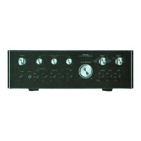
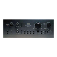
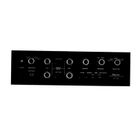
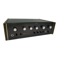
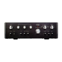
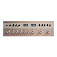
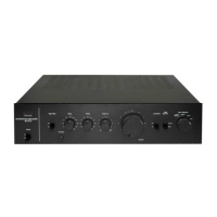
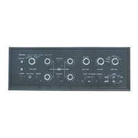
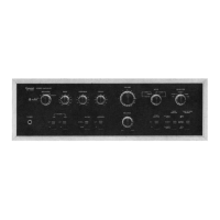
Lists and describes the function of front panel controls.
Shows component layout and identifies parts on the F-2596 circuit board.
Displays the physical layout and component identification for the F-2598 circuit board.
Details component layout and parts for the F-2599 equalizer circuit board.
Shows component layout for the F-2600 board connecting pre and main amplifiers.
Details component layout for the F-2601 board handling pick-up load switching.
Identifies components on the F-2602 lever switch circuit board.
Shows component layout for the F-2603 volume and balance circuit board.
Displays component layout for the F-2608 volume and balance circuit board.
Identifies components on the F-2609 lever switch circuit board.
Shows component layout for the F-2610 tone control circuit board.
Details component layout for the F-2611 filter circuit board.
Displays component layout for the F-2606 tone control circuit board.
Shows component layout for the F-2607 filter circuit board.
Details component layout for the F-2604 tone control circuit board.
Identifies components on the F-2605 filter unit circuit board.
Provides a parts list and exploded view of unit components.
Illustrates the operational flow of the power amplifier section.
Shows the functional overview of the power supply and protector circuits.
Guides on diagnosing issues within the power amplifier section.
Details troubleshooting steps for power supply and protector circuit problems.
Explains the functions of tone control settings and their indicators.
Presents the complete schematic diagram for the AU-5900 model.
Provides the schematic diagram for the AU-6900 model.
Presents the schematic diagram for the AU-7900 model.
Details the procedure for adjusting the driver circuit board bias.
Explains the steps for replacing power transistors on the amplifier.
Categorizes common resistors and capacitors by type and specification.
Explains how to read color codes for resistors.
Details various capacitor types, tolerances, and voltage ratings.
| Input Sensitivity | 2.5mV (MM), 150mV (line) |
|---|---|
| Channel Separation | 50dB (MM), 55dB (line) |
| Speaker Load Impedance | 8Ω to 16Ω |
| Total Harmonic Distortion | 0.1% |
| Damping Factor | 40 |
| Signal to Noise Ratio | 90dB (line) |
| Output | 150mV (line) |
| Type | Integrated Amplifier |