Do you have a question about the Sansui BA-3000 and is the answer not in the manual?
Details adjustments for the driver circuit board, including DC OV and bias current.
Details the procedure for adjusting the power meter for accurate readings.
Illustrates the operational flow of the unit's various sections for troubleshooting.
Provides a systematic guide for diagnosing and resolving common issues by section.
Lists parts and their locations for the F-2507 driver circuit board.
Lists parts and their locations for the F-2511 speaker protector circuit board.
Lists parts for the F-2510 circuit board for emitter installation.
Lists parts for the F-2514 meter lamp circuit board.
Lists parts for the F-2506 input terminal circuit board.
Lists parts for the F-2512 connector circuit board.
Lists parts and their locations for the F-2513 filter circuit board.
Lists parts and their locations for the F-2508 power supply voltage circuit board.
Lists parts and their locations for the F-2515 meter amplifier circuit board.
Lists parts for the F-2509 circuit board for installing the connector.
Visual representations of semiconductors and connectors used in the unit.
Instructions on how to change AC line voltage connections.
Identifies various internal and external components by location.
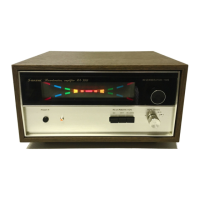
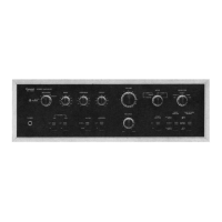
Illustrates the location of front panel components and hardware.
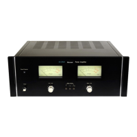
| Type | Stereo Power Amplifier |
|---|---|
| Speaker Load Impedance | 4Ω to 16Ω |
| Power Output | 150 watts per channel into 8Ω (stereo) |
| Frequency Response | 10Hz to 30kHz |
| Total Harmonic Distortion | 0.1% |
| Signal to Noise Ratio | 100dB |