Do you have a question about the Sansui B-2102 and is the answer not in the manual?
Details the minimum RMS power output for both channels driven.
Specifies the acceptable load impedance range for the amplifier.
Indicates the THD level at rated power output.
States the IM distortion level at rated power output.
Defines the frequency range and deviation for a 1W output.
Specifies input signal requirements and impedance.
Details the S/N ratio measured with a specific test condition.
Lists voltage and frequency requirements for operation.
Indicates the power draw in watts and VA.
Provides the physical size of the unit.
States the net and packed weight of the unit.
Identifies parts critical for safety, requiring specific replacements.
Advises on performing leakage current or resistance tests before returning to customer.
Illustrates the circuitry for the main power amplification stage.
Details the circuitry for the peak power metering function.
Component layout for the F-4618 drive amplifier board.
Component layout for the F-4619 power amplifier board.
Component layout for the F-4620 protector board.
Component layout for the F-4626 power supply board.
Component layout for the F-4628 AC fuse board.
Component layout for the F-5439 control board.
Component layout for the F-5433 power supply board.
Component layout for the F-5435 speaker switch board.
Component layout for the F-5436 display switch board.
Component layout for the F-5438 input terminal board.
Component layout for the F-5437 pilot lamp board.
Component layout for the F-5440 L-channel indicator board.
Component layout for the F-5441 R-channel indicator board.
Specific adjustment steps for the F-4618 flat amplifier board.
Adjustment procedures for the driver and power amplifier boards.
Procedure for calibrating the level meter display.
Adjusts the over swing indicator function.
Schematic for the power amplifier circuitry.
Schematic for the peak power meter circuitry.
Continuation of the power amplifier circuit schematic.
Continuation of the peak power meter circuit schematic.
Schematic for the protector circuitry.
Schematic for the power supply circuitry.
Continuation of the protector circuit schematic.
Continuation of the power supply circuit schematic.
Schematic for the AC fuse board.
Schematic for the control board.
List of components for the F-4618 drive amplifier board.
List of components for the F-4619 power amplifier board.
Continuation of the component list for the F-4619 power amplifier board.
List of components for the F-4620 protector board.
List of components for the F-4626 power supply board.
List of components for the F-4628 AC fuse board.
List of components for the F-5439 control board.
List of components for the F-5433 power supply board.
Continuation of the component list for the F-5433 power supply board.
List of components for the F-5440 indicator board.
List of components for the F-5435 speaker switch board.
List of components for the F-5436 display switch board.
List of components for the F-5438 input terminal board.
List of components for the F-5437 pilot lamp board.
List of components for the F-5441 indicator board.
Terminal functions for the MSL9356 meter drive IC.
Block diagram and terminal functions for the TA7318P meter drive IC.
Block diagram and terminal functions for the M5218 operation amplifier.
Block diagram and terminal functions for the TA7317P protector IC.
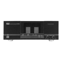
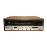
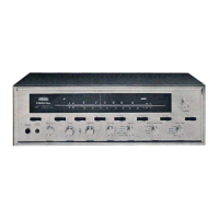
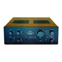
Labeled diagram of the amplifier's front panel controls and indicators.
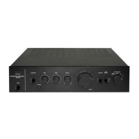
Labeled diagram showing component placement on the top internal chassis.
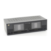
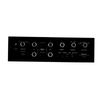
Labeled diagram of the amplifier's rear panel connections and controls.
List of parts and their stock numbers corresponding to front, top, and rear views.