EasyManua.ls Logo

Sanyo CE28CN8F-C User Manual

Sanyo CE28CN8F-C
16 pages
To Next Page IconTo Next Page
Page #1 background imageLoading...
Page #1 background image
Part No. SKSM0719 C5WYS JULY 2004
Colour Television
Service Manual
Model CE28CN8F-C
Service Ref. No. CE28CN8F-C-00
PRODUCT CODE: 111361018
ORIGINAL VERSION: Chassis No. EB8-A
Give complete "SERVICE REF. NO." for parts
order or servicing, it is shown on the rating sheet
on the cabinet back of the TV set.
Note
This TV receiver will not work properly in foreign
countries where the television transmission
system and power source differ from the design
specifications. Refer to the specifications for the
design specifications
CE28CN8F-C
Contents
Safety precautions/Specifications ..................................................................................................................2
Block diagrams ..............................................................................................................................................3
Cabinet Disassembly ......................................................................................................................................4
Adjustment and Repair Procedures............................................................................................................5~9
CPU Functions ..............................................................................................................................................................................10~11
Component Locations ..................................................................................................................................12
IC Block Diagrams..................................................................................................................................13~15
Pin description of semiconductors................................................................................................................16
Part Description and reading of schematic diagram ....................................................................................17
Cabinet Parts List/TV Stand parts list ..........................................................................................................18
Electric Parts List....................................................................................................................................19~24
Please use Schematic Diagram SKP20442
inserted with this Service Manual.
Question and Answer IconNeed help?

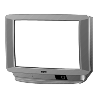
Do you have a question about the Sanyo CE28CN8F-C and is the answer not in the manual?

Sanyo CE28CN8F-C Specifications

General IconGeneral
BrandSanyo
ModelCE28CN8F-C
CategoryTV
LanguageEnglish

Summary

Block Diagram Overview

Diagram Outline

Provides a general overview of the block diagram's structure and components.

TV Option Settings

Entering Option Mode

Instructions to access the TV's option setting menu via remote and front panel.

Configuring Option Items

Details on navigating and modifying various option settings within the menu.

Service Adjustments and Geometry Data

Adjustable Service Parameters

List of OSD adjustable service parameters for fine-tuning TV performance.

Picture Geometry Data Points

Specific service data points related to picture geometry adjustments.

Service Mode and Memory IC

Accessing Service Mode

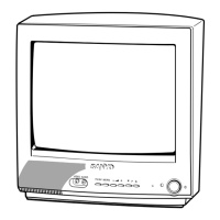
Procedures for accessing and leaving the TV's service mode using remote and mains switch.

Memory IC Initialization Procedure

Steps to reset the memory IC to default values after replacement.

Picture and Signal Adjustments

+B Voltage Calibration

Procedure for adjusting the +B voltage to the specified level.

PCC (Picture Chrominance Consistency)

Adjusting Picture Chrominance Consistency for optimal color.

AGC (Automatic Gain Control) Setup

Procedure for setting the Automatic Gain Control voltage.

Focus Control Adjustment

Adjusting the focus control for a sharp picture.

Picture Geometry and OSD Adjustments

Corner and Trapezoid Correction

Correcting distortion in the picture corners and trapezoidal shape.

Vertical and Horizontal Centering

Adjusting the vertical and horizontal positioning of the picture.

Vertical Height and Width Settings

Setting the overall vertical height and horizontal width of the picture.

High-Voltage Output Confirmation

Procedure for confirming the high-voltage output to the CRT.

OSD Positioning Tuning

Adjusting the position of on-screen display elements.

CPU Port Functionality

CPU Pinout and Functions

Detailed listing of CPU pins, their names, functions, and I/O direction.

Chassis Electrical Parts Catalog

Capacitor Specifications

List of capacitor types, values, and part numbers.

Resistor Specifications

List of resistor types, values, and part numbers.

Coil Specifications

List of coil types, values, and part numbers.

Picture Tube Assembly

Information and part number for the CRT assembly.

Miscellaneous Component Listings

List of other electronic components and their details.

Related product manuals