D
Daniel BeasleyAug 8, 2025
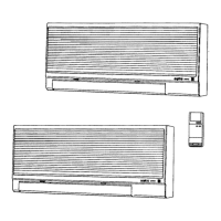
Why is my Sanyo Air Conditioner indoor unit not operating?
- DDouglas FullerAug 8, 2025
If your Sanyo Air Conditioner's indoor unit isn't working, there could be several reasons. Check if the operation lamp is blinking or not illuminated at all. Also, verify if the indoor and outdoor fans are turning, and whether the outdoor unit and compressor are operating. The compressor might stop occasionally, its speed might not increase, or the electric expansion valve could be malfunctioning. Finally, ensure that the unit is cooling adequately.