- 69 -
IC BLOCK DAIGRAM & DESCRIPTION
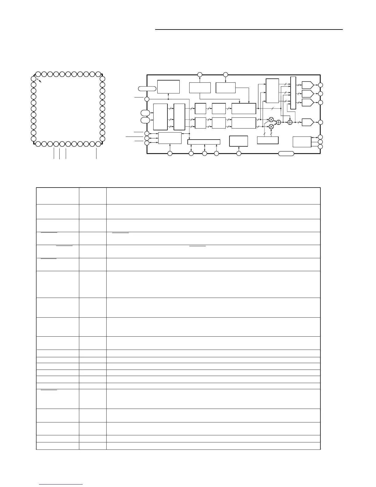
IC102 ADV7170KSU (VIDEO Encoder)
1
2
3
4
5
6
7
8
9
10
11
12 13 14 15 16 20 21 2217 18 19
44 43 42 41 40 36 35 3439 38 37
33
32
31
30
29
28
27
26
25
24
23
V
AA
P5
P6
P7
P8
P9
P10
P11
P12
GND
V
AA
CLOCK
GND
P4
P3
P2
P1
P0
TTX
TTXREQ
SCRESET/
RTC
R
SET
V
REF
DAC A
DAC B
V
AA
GND
V
AA
DAC D
DAC C
COMP
SDATA
SCLOCK
P13
P14
P15
ALSB
GND
V
AA
GND
RESET
BLANK
HSYNC
FIELD/VSYNC
ADV7170/ADV7171
PQFP/TQFP
TOP VIEW
(Not to Scale)
PIN 1
IDENTIFIER
POWER
MANAGEMENT
CONTROL
(SLEEP MODE)
CGMS & WSS
INSERTION
BLOCK
TELETEXT
INSERTION
BLOCK
4:2:2 TO
4:4:4
INTER-
POLATOR
YCrCb
TO
YUV
MATRIX
ADD
SYNC
INTER-
POLATOR
INTER-
POLATOR
ADD
BURST
PROGRAMMABLE
LUMINANCE
FILTER
PROGRAMMABLE
CHROMINANCE
FILTER
VIDEO TIMING
GENERATOR
I C MPU PORT
2
REAL-TIME
CONTROL
CIRCUIT
SIN/COS
DDS BLOCK
VOLTAGE
REFERENCE
CIRCUIT
10-BIT
DAC
10-BIT
DAC
10-BIT
DAC
10-BIT
DAC
YUV TO
RBG
MATRIX
M
U
L
T
I
P
L
E
X
E
R
U
U
10
10
10 10
10
10
10
10
10
10
10
10
V
V
88
9
8
8
9
88
8
88
8
44 23 24 18 35
32
31
26
27
3736
22
16
15
17
34
33
25
Y
1,11,20,28,30
4-2
43-38
14-12
9-5
10,19,29,43
Vss
CLOCK
DATA
P7-P0
P15-P8
RESET
HSYNC
FIELD/VSYNC
BLANK
CLOCK SCLOCK SDATA ALSB SCRESET/RTC GND
COMP
DAC A(PIN 32)
GAC B(PIN 31)
DAC C(PIN 26)
DAC D(PIN 27)
R
SET
V
REF
TTXREQ TTX
Input/
Output
I
I
I/O
I/O
I/O
I
I/O
I
O
O
O
O
O
I
I/O
I
I
I
O
P
G
Function
8-Bit 4:2:2 Multiplexed YCrCb Pixel Port (P7-P0) or 16-Bit YCrCb Pixel Port (P15-P0).
P0 represents the LSB.
TTL Clock Input. Requires a stable 27 MHz reference Clock for standard operation. Alter-
natively, a 24.52 MHz (NTSC) or 29.5 MHz (PAL) can be used for square pixel operation.
HSYNC (Modes 1 and 2) Control Signal. This pin may be configured to output (Master
Mode) or accept (Slave Mode) Sync signals.
Dual Function FIELD (Mode 1) and VSYNC (Mode 2) Control Signal. This pin may be
configured to output (Master Mode) or accept (Slave Mode) these control signals.
Video Blanking Control Signal. The pixel inputs are ignored when this is Logic Level "0."
This signal is optional.
This pin can be configured as an input by setting MR22 and MR21 of Mode Register 2. It
can be configured as a subcarrier reset pin, in which case a high-to-low transition on this
pin will reset the subcarrier to Field 0. Alternatively, it may be configured as a Real-Time
Control (RTC) input.
Voltage Reference Input for DACs or Voltage Reference Output (1.235 V).
A 150 Ω resistor connected from this pin to GND is used to control full-scale amplitudes of
the video signals.
Compensation Pin. Connect a 0.1 µ F Capacitor from COMP to VAA. For Optimum Dynamic
Performance in low power mode, the value of the COMP capacitor can be lowered to as low
as 2.2 nF.
PAL/NTSC Composite Video Output. Full-Scale Output is 180 IRE (1286 mV) for NTSC
and 1300 mV for PAL.
RED/S-Video C/V Analog Output.
GREEN/S-Video Y/Y Analog Output.
BLUE/Composite/U Analog Output.
MPU Port Serial Interface Clock Input.
MPU Port Serial Data Input/Output.
TTL Address Input. This signal set up the LSB of the MPU address.
The input resets the on chip timing generator and sets the ADV7170/ADV7171 into default
mode. This is NTSC operation, Timing Slave Mode 0, 8 Bit Operation, 2 x Composite and
S Video out and DAC B powered ON and DAC D powered OFF.
Teletext Data/Defaults to VAA When Teletext not Selected (enables backward compatibility to
ADV7175/ADV7176).
Teletext Data Request Signal/ Defaults to GND when Teletext not Selected (enables backward
compatibility to ADV7175/ADV7176).
Power Supply (+3V to +5V).
Ground Pin.
Mnemonic
P15-P0
CLOCK
HSYNC
FIELD/VSYNC
BLACK
SCRESET/RTC
V
REF
R
SET
COMP
DAC A
DAC C
DAC D
DAC B
SCLOCK
SDATA
ALSB
RESET
TTX/V
AA
TTXREQ/GND
V
AA
GND
 Loading...