EasyManua.ls Logo

Sanyo KHS2672R User Manual

Sanyo KHS2672R
2 pages
To Next Page IconTo Next Page
Page #1 background imageLoading...
Page #1 background image
System: 26KHS72R Indoor/Outdoor: KHS2672R/CH2672R
Wall Mounted Heat Pump
Power V/PH/Hz 230/208/1/60
Circuit Ampacity
Fuse Size, Max.
Compressor
No. used
R.L. Amps - L.R.
Outdoor Unit
Fan type
Dia. (in.) - No. Speeds
Type Drive - No. Speeds
No. Poles
No. Motors
CFM
F.L. Amps
Coil Type
Fin Type - Pipe Type
Rows - F.P.I.
Face Area
Tube Size
Indoor Unit
Fan type
Dia. & Length (in.) - No. Speeds
No. Speeds
No. Poles
No. Motors
CFM
Indoor Sound Rating
F.L. Amps
Coil Type
Fin Type - Pipe Type
Rows - F.P.I.
Face Area
Tube Size
Drain Connection Size
Refrigerant
Lbs. - R410a (outdoor unit)
Control
Connection
Line Length, Max (ft.)
Lift Difference, Max (ft.)
Line Size
Line Size
Dimensions
Indoor Unit
Outdoor Unit
Weight
Net
Shipping
Shipping Volume
Performance Data @ ARI Standard Conditions (230/208V)
Cooling
Total Capacity
Sensible Capacity
Latent Capacity
SEER
Dehumidification
Amps
Power Inputs
Outdoor Sound Rating
Heating
Total Capacity
HSPF
(A) 15-30 Indoor-Outdoor
General Data (at 230V)
1
(A) 12.9-17.5
Propeller
18-7/64-1
DC Motor
(RPM) 8 - 800
(W) 1 - 90
14.9
(Pints/H) 8.1
(BTU/H) 25,200 (9,500-25,200)
(BTU/H) 14,790
(BTU/H) 10,410
(Uncrated) 12-63/64 x 44-7/8 x 8-31/32
(W) 2,840/2,840
Aluminum Fin & Copper Pipe
Slit Plate - Inner Riffeled
(in.) 3/8”
4.19
Split System Submittal Data
Electric Expansion Valve
Job Name:
Location:
Engineer:
Submitted to:
Submitted by:
Reference:
Approval:
Date:
Construction:
Unit #:
Drawing #:
1 - 15.9
(sq.ft.) 7.26
(lbs.) 40 128
(A) 15.3/16.9
(in. O.D. Discharge) 3/8”
(in. O.D. Suction) 5/8”
DC Rotary Inverter
(High) 1765
(A) 13.8
R410A
(in.) H x W x D
(Crated) 15-11/32 x 47-27/32 x 11-17/32
Indoor Outdoor
(cu.ft.) 4.9 13.0
Indoor Outdoor
(lbs.) 44 148
(dB-A) 49
Cross Flow
3-15/16 L33-15/64 - 1
3 & Auto
(RPM, High) 4 - 1224
(W) 1 - 29
Aluminum Plate Fin & Copper Tube
Slit Plate - Inner Riffeled
(in.) 9/32”
2 - 24.1
(sq.ft.) 2.57
(HI/Med/Lo) 559/475/390
(A) 0.31
(in.) 1-1/4”
(Hi) (dB-A) 48
Flare
165
50 (outdoor lower), 100 (outdoor higher)
(Uncrated) 30-23/32 x 37 x 13-3/8
(Crated) 34-31/32 x 39-31/32 x 16-3/32
10.2
(BTU/H) 29,200 (8,000-29,200)
Question and Answer IconNeed help?

Do you have a question about the Sanyo KHS2672R and is the answer not in the manual?

Sanyo KHS2672R Specifications

General IconGeneral
BrandSanyo
ModelKHS2672R
CategoryAir Conditioner
LanguageEnglish

Summary

General Data and Specifications

Power and Compressor Specifications

Electrical input requirements and compressor details including voltage, ampacity, fuse size, and operating amps.

Outdoor Unit Details

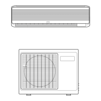
Specifications for the outdoor unit's fan, motor, coil type, and physical dimensions.

Indoor Unit Details

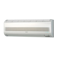
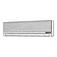
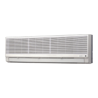
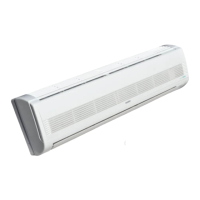
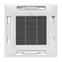
Specifications for the indoor unit's fan, motor, coil type, sound rating, and physical dimensions.

System and Performance Parameters

Refrigerant and Connection Data

Information on refrigerant type, charge, connection type, line length, and lift differences.

Unit Dimensions

Physical dimensions for both indoor and outdoor units in both uncrated and crated states.

Weight and Shipping Volume

Net and shipping weight details for indoor and outdoor units, along with shipping volumes.

Cooling Performance Data

Performance metrics for cooling mode including capacity, SEER, dehumidification, and power input.

Heating Performance Data

Performance metrics for heating mode including total capacity and HSPF.

Operational Features and Controls

Heating Specifications

Heating operational parameters such as amperage, power input, and backup strip heater.

System Features

Key features including controls, timer, night setback, air louvers, and air filter.

Operating Range

Indoor and outdoor air intake temperature ranges for cooling and heating modes.

System Diagrams and Components

Unit Dimensions Diagram

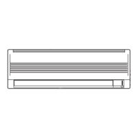
Visual representation of unit dimensions with key measurements indicated.

Component and Connection Details

Diagrams illustrating component placement and refrigerant line connection points.

Related product manuals