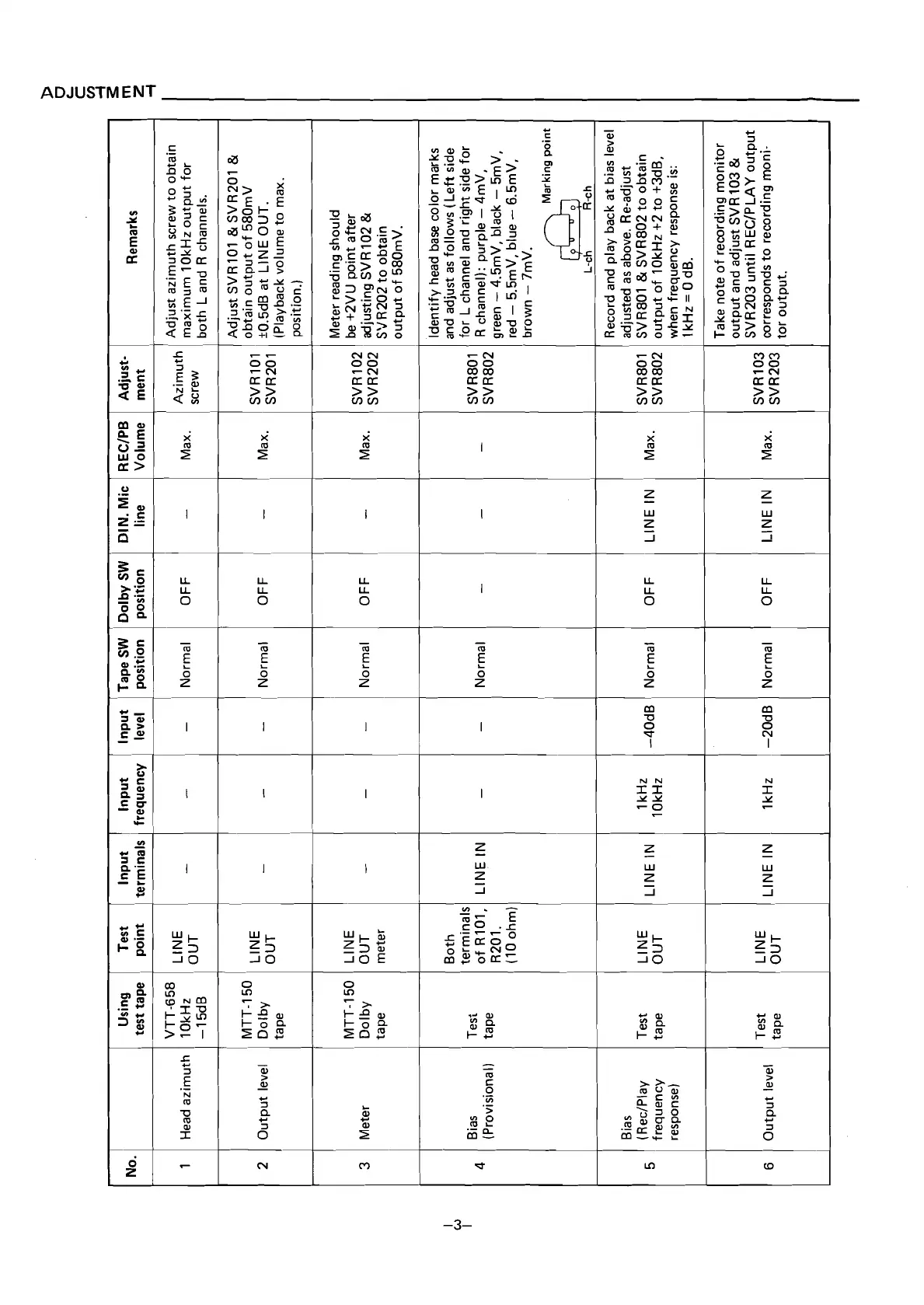
No.
Using Test Input
Input Input Tape
SW
Dolby
SW
DIN. Mic RECIPB Adjust-
test tape point terminals frequency level position position line Volume ment
Remarks
VTT-658
Adjust azimuth screw to obtain
1 Head azimuth
10kHz
-
-
-
Normal OFF
-
OUT
Azimuth
maximum 10kHz output for
-1 5dB
screw
both L and
R channels.
1
Adjust SVR101
&
SVR201
&
I
MTT-150
1
obtain output of 580mV
2 Output level Dolby
-
Normal OFF
I
-
I
Max.
OUT
SVR1O1
k0.5dB at LlNE OUT.
tape
SVR201
(Playback volume to max.
position.)
Meter reading should
MTT-150 LINE
SVR
02
be +2VU point after
3 Meter Dolby OUT
- -
Max.
SVR202
adjusting SVR 102
&
meter S'JR202 to obtain
'
6
Bias
(Provisional)
Bias
(
RecIPlay
frequency
response)
Output level
Tesi
tape
Test
tape
Test
Both
terminals
of
R101,
R201.
(10 ohm)
LINE
OUT
LINE IN
LINE IN Normal
-
tape
1
LINE IN
-
LINEIN
LINEIN)
Normal
1kHz -20dB
OFF
-
-4OdBINormal
corresponds to recording rnoni-
tor output.
Max.
OFF
'
SVR103
SVR203
Max.
SVR801
&
SVR802 to obtain
output of 10kHz +2 to +3dB,
when frequency response is:
1 kHz
=
0 dB.
Take note of recording monitor
output and adjust
SVR103
&
SVR203 until RECIPLAY output
SVR801
SVR802
output of 580mV.
Identify head base color marks
and adjust as follows (Left side
for L channel and right side for
R channel): purple
-
4mV,
green
-
4.5mV, black
-
5mV.
red
-
5.5mV. blue
-
6.5mV.
brown
-
7mV.
Marking
point
L-ch
R-ch
Record and play back at bias level
adjusted as above. Re-adjust
 Loading...