ADJUSTMENT OF PINCH ROLLER
Tape:
Recording system:
,Erasing system:
Tape speed:
Rewind
81
Fast
forward time:
Wow
81
Flutter
Bias frequency:
Distortion
Frequency response:
Signal to noise ratio:
Terminal impedance:
(Input)
(Output)
Power source
Dimensions:
Weight:
Chromium dioxide or normal cassette tape
AC bias, 114 track stereo
AC erase, 112 track
1-718 ips. (4.75 cmlsec.)
90 sec. (C-60)
0.1 5% RMS
67
-
73 KHz
Less than 1%
(1 KHz, -60dB)
30
-
13,000Hr (Normal tape)
30
-
16,000Hz (Chromium dioxide tape)
Dolby N.R. OFF: 50dB
ON
:
58dB
MIC:
10K ohms (0.25mV)
LlNE IN: 60K ohms (63mV)
RECIPB: 10K ohms (1mV)
LlNE OUT: 5K ohms (500mV)
RECIPB: 5K ohms (500mV)
HEADPHONE: 8
-
10K ohm
AC:
120120012201240V 50160Hz (RD4080)
11011251220V 50160Hr (RD4080UM)
240V 50160Hz (RD4080AUST.).
15-114"(W)
x
10"(D)
x
4-318"(H)
(386 x256x lllmm)
Approx. 8 Ibs. 2 02s. (3.7Kg)
1. Set the unit to the PLAY mode.
2. Apply a tension gauge to the pinch roller. Read the gauge at the
precise moment when the pinch rolier separates from the capstan.
3. If the gauge reading is within a range of more than 200 g,
noadjust-
ment is necessary. If otherwise, make adjustment by changing the
force of the spring coil. (See exploded view No.
23)
TORQUE ADJUSTMENT
1. Set the unit to the PLAY, FAST FORWARD or REWIND mode.
2. Measure the each torque with a torque gauge. They should be as
following;
PLAY 30
-
60 glcm
FAST FORWARD
55
-
110 glcm
REWIND
55
-
110 glcm
3. If the each torque fails to reach the standard value. Clean the drive
belt, flywheel, motor pulley, take-up reel, idler and rewind roller
with a cotton swab soaked in alcohol.
AUTO SHUT-OFF ADJUSTMENT
1. Set the unit to the PLAY mode.
2. Apply a tension gauge to the sensor. Push the gauge and measure
the sensor pressure.
3. The sensor pressure should be 30
-
50 g.
4. If a sensor pressure of more than 50 g, or less than 30
g,
adjust the
spring coil (See exploded view No. 25).
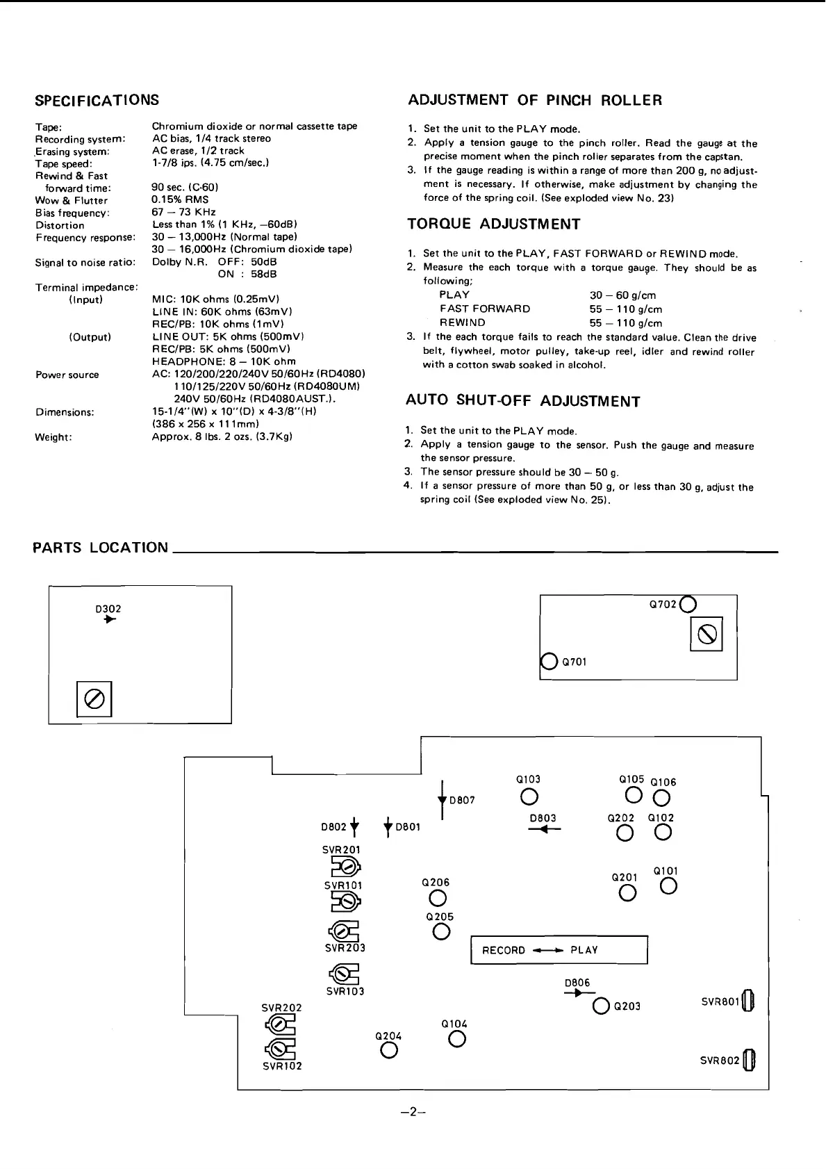
PARTS LOCATION
D302
+
Q103
Q105
Q106
1
0
-
0803
00
D802
t
)~801
Q202 Q102
+
SVR201
0
0
EB
Q201 Ql 01
SVRlOl (2206
B
0
0
0
Q205
a
SVR203
0
@
D806
SVR103
SVR202
-0
Q203 SVR8010
4z
Q104
a
Q204
0
0
SVRlO2
SVRBO2
0
RECORD
-
PLAY
 Loading...